SLVUBZ2A September 2020 – December 2020 LM5127-Q1
7.3 EVM Modification Test Setups
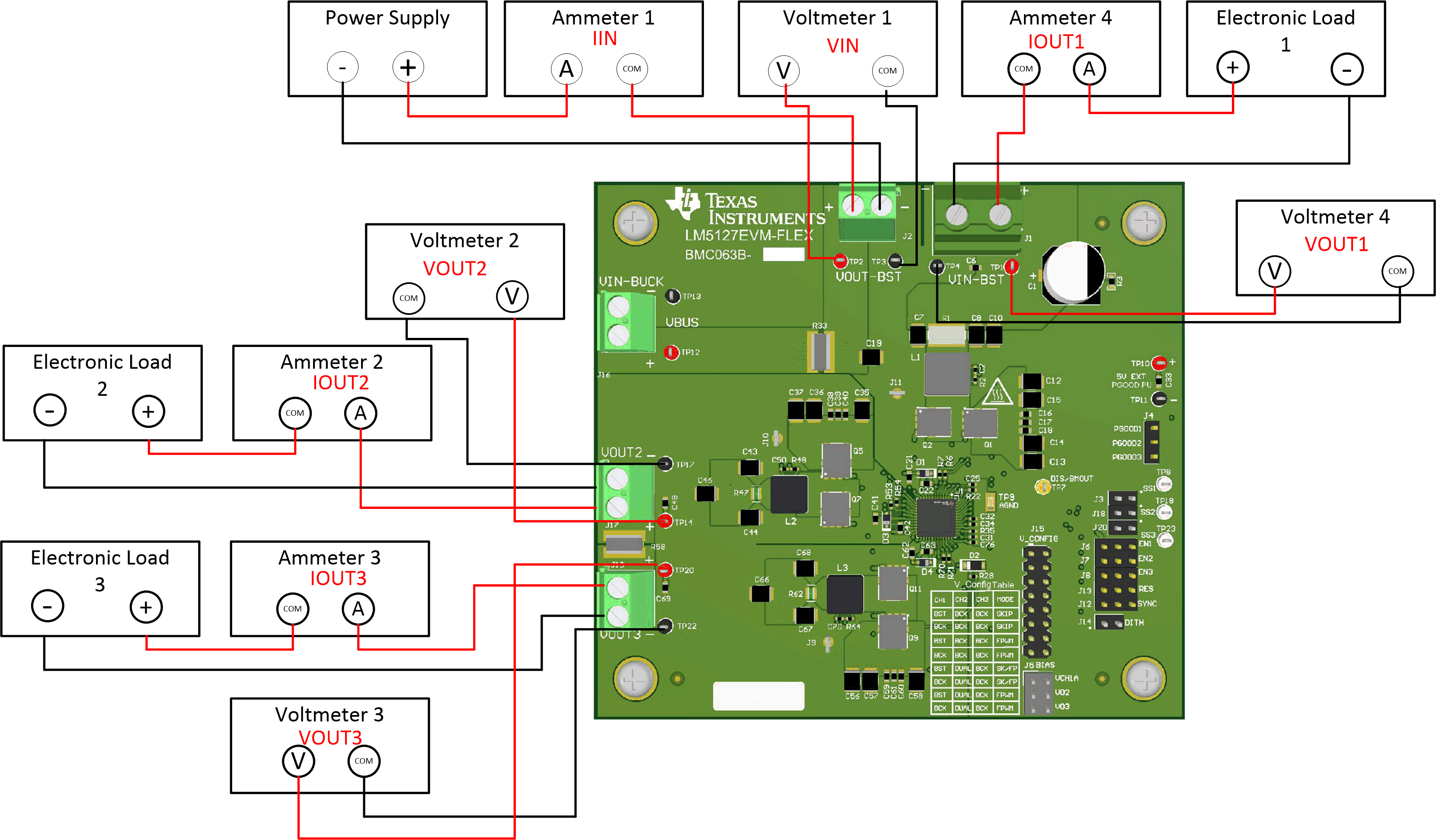
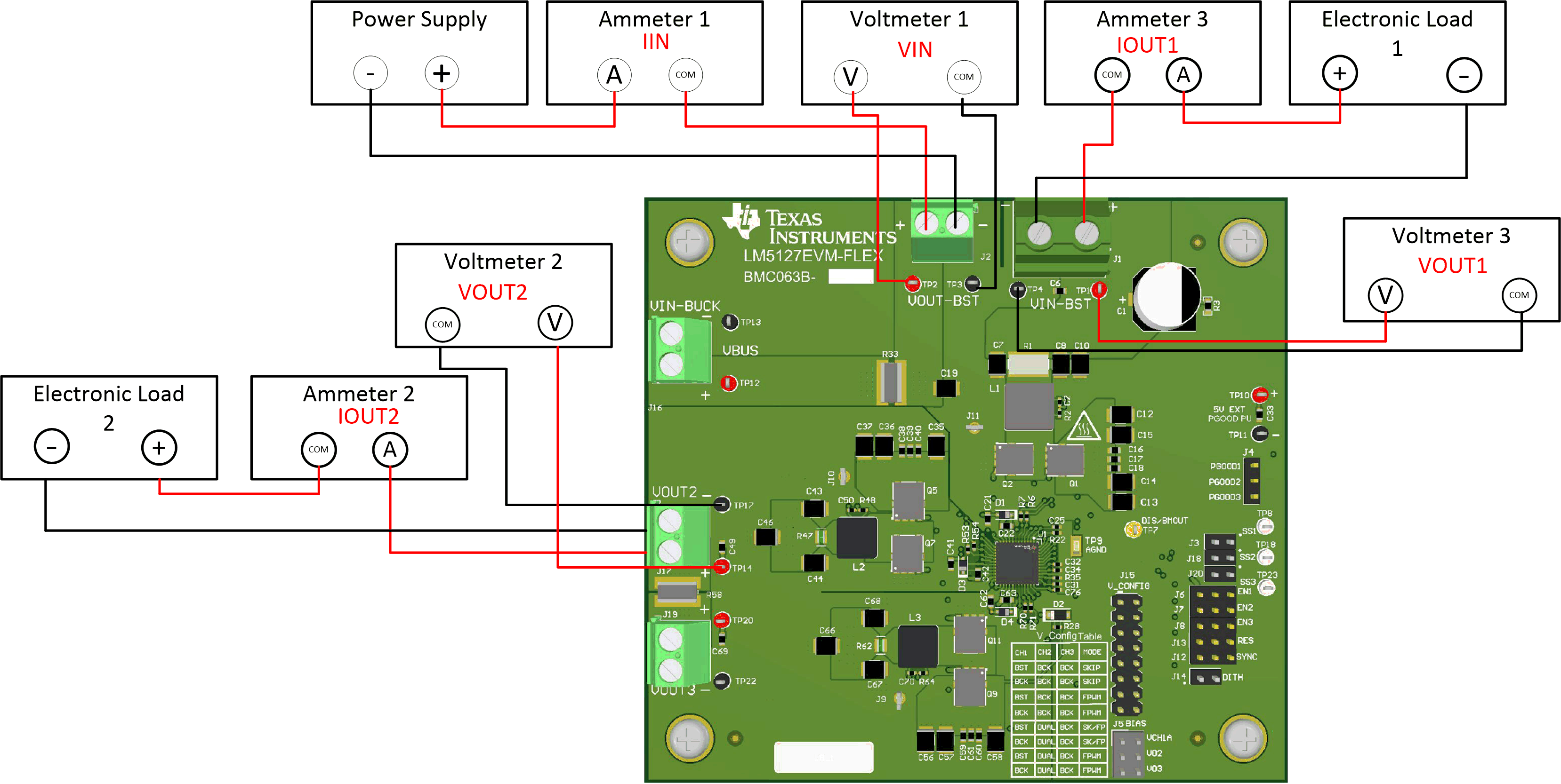
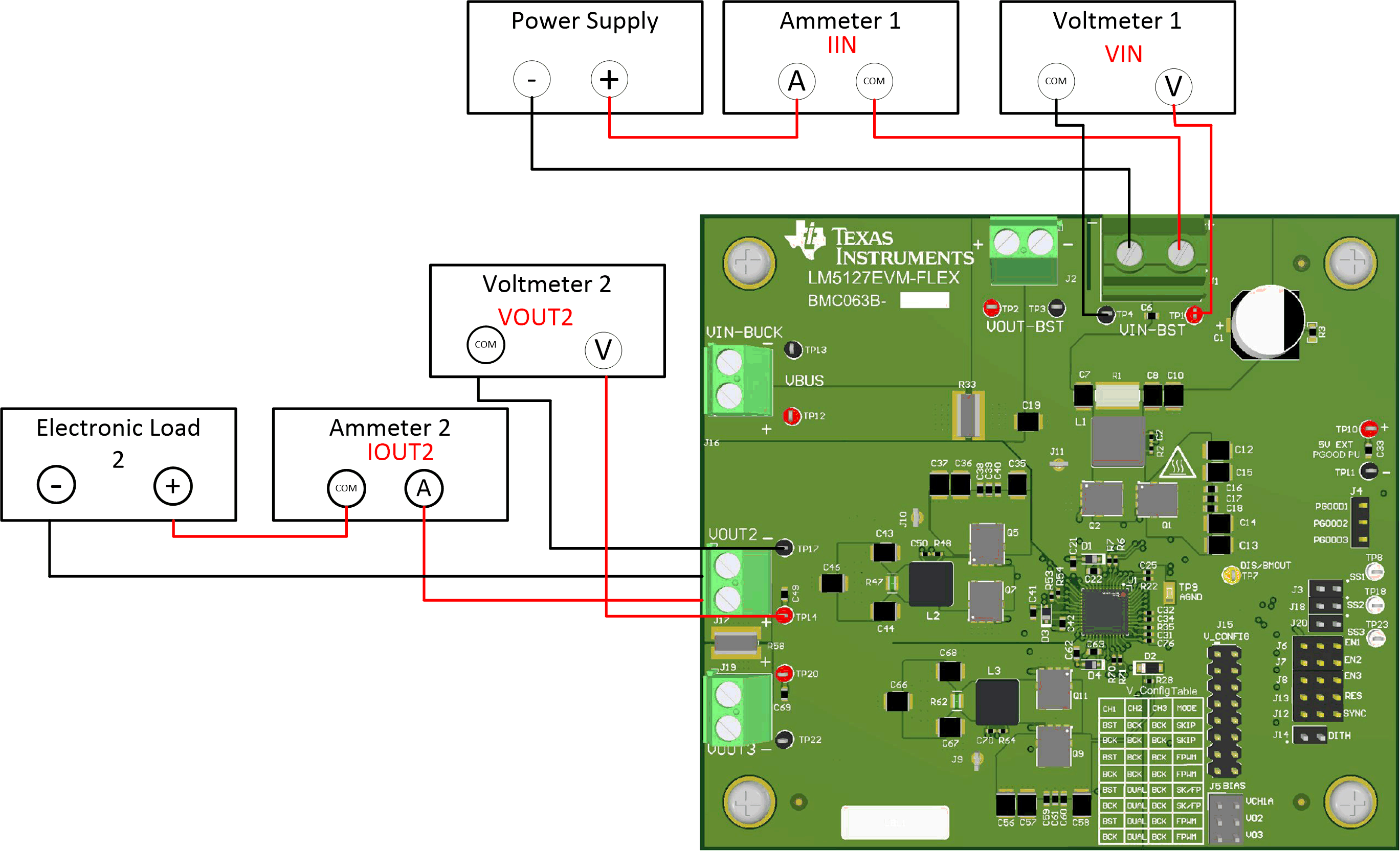
Figure 7-4 through Figure 7-6 show how to properly setup the evaluation module for the configurations described in Section 7.1 and Section 7.2.
 Figure 7-4 Channel 1 as a Buck Controller,
Channel 2 and Channel 3 as Independent Buck Controllers
 Figure 7-5 Channel 1 as a Buck Controller,
Channel 2 and Channel 3 as Dual Phase Buck Controller
 Figure 7-6 Channel 1 as a Boost Controller,
Channel 2 and Channel 3 as a Dual Phase Buck Controller