SLVUCP8 September 2024 TPS26750
- 1
- Description
- Get Started
- Features
- Applications
- 6
- 1Evaluation Module Overview
- 2Hardware
-
3Software
- 3.1 Software Description
- 3.2 Software Installation
- 3.3 Software Development
- 3.4 Using the Application Customization Tool
- 4Application Specific Use Cases
- 5Hardware Design Files
- 6Additional Information
3.4.3 Filling Out the Questionnaire
After making a selection for Question 1, answer the remaining questions to enable flashing a TPS26750EVM or to generate and save a full configuration. Based on the selection for Question 1, some of the remaining questions can be unavailable for selection.
Questionnaire Explanation
Question 1: Section 3.4.2
Question 2: What is the maximum power in Watts that you want to source from the TPS26750EVM using the DUT Type C Port (J4)? If a sink only configuration was selected, this question is not selectable.
When selecting the maximum power that can be sourced, the Transmit Source Capabilities register (0x32) of the TPS26750 is configured by adding default Source PDOs (each PDO is also referred to as a USB-PD contract) as shown in Figure 3-6.
Question 3: What is the maximum power in Watts that you want to sink to the TPS26750EVM using the DUT Type C Port (J4)? If a source only configuration was selected, then this question is not selectable.
When selecting the maximum power that can be sinked, the Transmit Sink Capabilities register (0x33) of the TPS26750 is configured by adding default Sink PDOs (each PDO is also referred to as a USB-PD contract).
| Power Option Selected | Default SPR PDOs |
|---|---|
| 15W (5V) | 5V/3A |
| 27W (9V) | 5V/3A, 9V/3A |
| 45W (15V) | 5V/3A, 9V/3A, 15V/3A |
| 60W (20V) | 5V/3A, 9V/3A, 15V/3A, 20V/3A |
| 100W (20V) | 5V/3A, 9V/3A, 15V/3A, 20V/5A |
The PDOs included in Registers 0x32 and 0x33 are correlated with the selected power option in Table 3-2.
If required power is greater than 100W, and an option greater than 100W is selected, then the PDOs greater than 100W are EPR PDOs, and the default generated PDOs are shown in Table 3-3. The PDOs are listed in order. A single fixed PDO is listed in the format [PDO Voltage value]V/[PDO Current value]A:
| Power Option Selected | Default SPR PDOs | Default EPR PDOs |
|---|---|---|
| 140W (28V) | 5V/3A, 9V/3A, 15V/3A, 20V/5A | 28V/5A, AVS PDO |
| 180W (36V) | 5V/3A, 9V/3A, 15V/3A, 20V/5A | 28V/5A, 36V/5A, AVS PDO |
| 240W (48V) | 5V/3A, 9V/3A, 15V/3A, 20V/5A | 28V/5A, 36V/5A, 48V/5A, AVS PDO |
Question 4: If a DRP configuration is selected in question 1 (Configuration Index 1 or 2), then question 4 determines which power role (source or sink) is preferred by the TPS26750EVM. If Configuration Index 3,4, or 5 was selected, then this question is not selectable. The meaning of preferred in this context is the following:
- If the TPS26750EVM prefers to be a source, and after connection to a port partner, is acting as a sink, then the TPS26750 requests to the port partner to swap roles (power role swap) in an attempt to become a power source.
- If the TPS26750EVM prefers to be a sink, and after connection to a port partner, is acting as a source, then the TPS26750 requests to the port partner to swap roles (power role swap) in an attempt to become a power sink.
Question 5: What is the supported USB speed of the DUT? Based on the selection, this determines what USB speed is enumerated during PD negotiation. If USB data is not required, then select No USB data is being used.
Question 6: What is the preferred data role (UFP, DFP, or Dual Role Port (different from Dual Role Power, a power role)) of the DUT? When an implicit Type-C contract (this occurs before the explicit USB-PD contract) is made the Power-role and Data-role is either Source and DFP or Sink and UFP. If this combination does not meet the USB Data Role needs for the application, then selecting the preferred data role allows the TPS26750 to request a data role swap when appropriate. If there is no preference, then select No. This information is stored in the Port Control register (0x29).
Question 7: Is USB Battery Charging 1.2 (BC1.2) and legacy charging supported in the application? Based on the selection, the TPS26750 can enumerate different BC1.2 charging schemes. Refer to the TPS26750 USB Type-C® and USB PD Controller with Integrated Power Switches Optimized for Power Applications data sheet for more details on BC1.2 implementation.
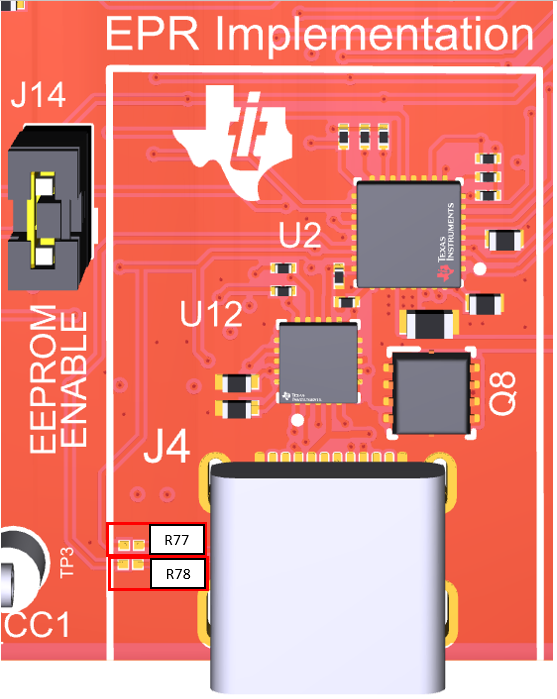
 Figure 3-3 Resistor 77 and 78
Location
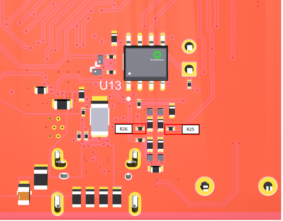
 Figure 3-4 Resistor 25 and 26
Location
Figure 3-4 Resistor 25 and 26
LocationQuestion 8: Enables or disables Liquid Detection support. This is a new feature of the TPS26750 based on the Type-C specification for Liquid Detection and Corrosion Mitigation. For more details, refer to Section 4.1.
Question 9: Allows the ability to enter a Vendor ID. The Vendor ID is given by the USB-IF, and is a 4-digit hexadecimal value. Select Yes option to enter the desired Vendor ID, otherwise select No.
Question 10: Allows the ability to enter a Product ID, which is a 4-digit hexadecimal configuration identifier, after selecting Yes. If unused, select No.
Questions 11 through 18 corresponds to configuring the selected BQ (Battery Charger) device if applicable. These questions are only available for use if a configuration was selected in the first question that includes a BQ block. For all other configurations (TPS26750 without a BQ block), these questions are disabled. For more details on each question, refer to Section 4.2.2.
The TPS26750 supports integration with the BQ25756 IC. If using the BQ25756EVM in conjunction with the TPS26750EVM, then any configuration in Question 1 with a BQ block can be used.