SLVUCP8 September 2024 TPS26750
- 1
- Description
- Get Started
- Features
- Applications
- 6
- 1Evaluation Module Overview
- 2Hardware
-
3Software
- 3.1 Software Description
- 3.2 Software Installation
- 3.3 Software Development
- 3.4 Using the Application Customization Tool
- 4Application Specific Use Cases
- 5Hardware Design Files
- 6Additional Information
4.1.1 Liquid Detection and Corrosion Mitigation Hardware Setup
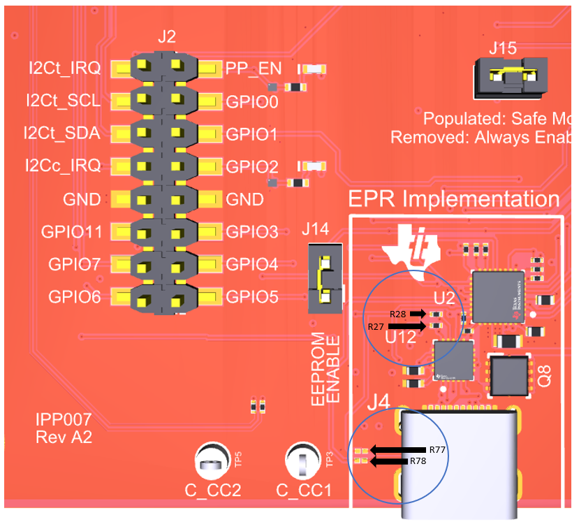
Out of the box, the hardware on the TPS26750EVM is set up for Liquid Detection and Corrosion Mitigation. R27 and R28 are populated to connect J4 Type-C SBU pins to TPS26750 GPIO4 and GPIO5 for liquid detection. R77 and R78, used for BC1.2, are not populated. TPD4S480 (U12) is in between the TPS26750 and the J4 Type-C port for short protection.
Resistors R27 and R28 are located to the left of U2, located in the EPR Implementation box. Pads for resistors R77 and R78 are located to the left of J4, in the EPR Implementation box. For location details, refer to Figure 4-2.
 Figure 4-2 Liquid Detection Resistor
Location
Figure 4-2 Liquid Detection Resistor
LocationOn the TPS26750EVM, the hardware is set to use specific GPIOs for MOSFET control and Liquid Detection feature. For user applications, some GPIOs can be configured differently while some are required for all designs. For details on specific test point and the configurability for custom designs, refer to Table 4-1. To setup liquid detection evaluation on the TPS26750EVM, refer to Section 4.1.2.
| Test Point on EVM | Description | Configurability |
|---|---|---|
| GPIO4 | Connected to SBU1 for Liquid Detection 1 (LD1) | Not configurable for custom designs |
| GPIO5 | Connected to SBU2 for Liquid Detection 2 (LD2) | Not configurable for custom designs |
| SBU1 | Connected to GPIO4 for Liquid Detection 1 (LD1) | Not configurable for custom designs |
| SBU2 | Connected to GPIO5 for Liquid Detection 2 (LD2) | Not configurable for custom designs |
| GPIO6 | Connected to PFET (QP1 and QP2) to enable pull-up, when enabled PD is detecting short to GND | Configurable for custom designs |
| GPIO7 | Connected to NFET (QN1 and QN2) to enable pull-down, when enabled PD is detecting short to VBUS/CC | Configurable for custom designs |
| GPIO1 | When Liquid Detect support is turned on in the questionnaire, this GPIO is the default output for the liquid_detected GPIO event. See TPS26750 Technical Reference Manual for details. | Configurable for custom designs |