An electric motor drive is an electrical system that provides a variable frequency output to an electric motor to drive industrial loads such as heating and air-conditioning, ventilation, pumps, compressors, and elevators, and factory automation loads such as conveyor belts, mining, and papermill equipment.
Electric motor drives in industrial environments experience conditions such as high temperatures and high humidity, AC power-line fluctuations, and mechanical overloads. Users are demanding greater efficiency, along with more reliability. The switching speeds of power semiconductor devices such as insulated-gate bipolar transistors (IGBTs) are continuously increasing, with greater adoption of wide-bandgap technologies such as silicon carbide (SiC) and gallium nitride (GaN) that enable faster switching speeds. Given the increasing need for higher switching speeds and more system reliability, modern motor-drive systems must both detect and protect against several fault events to minimize industrial equipment downtime.
In this article, I will discuss the priority level and impact of different fault events, along with how to detect them to prevent damage to motor-drive circuits.
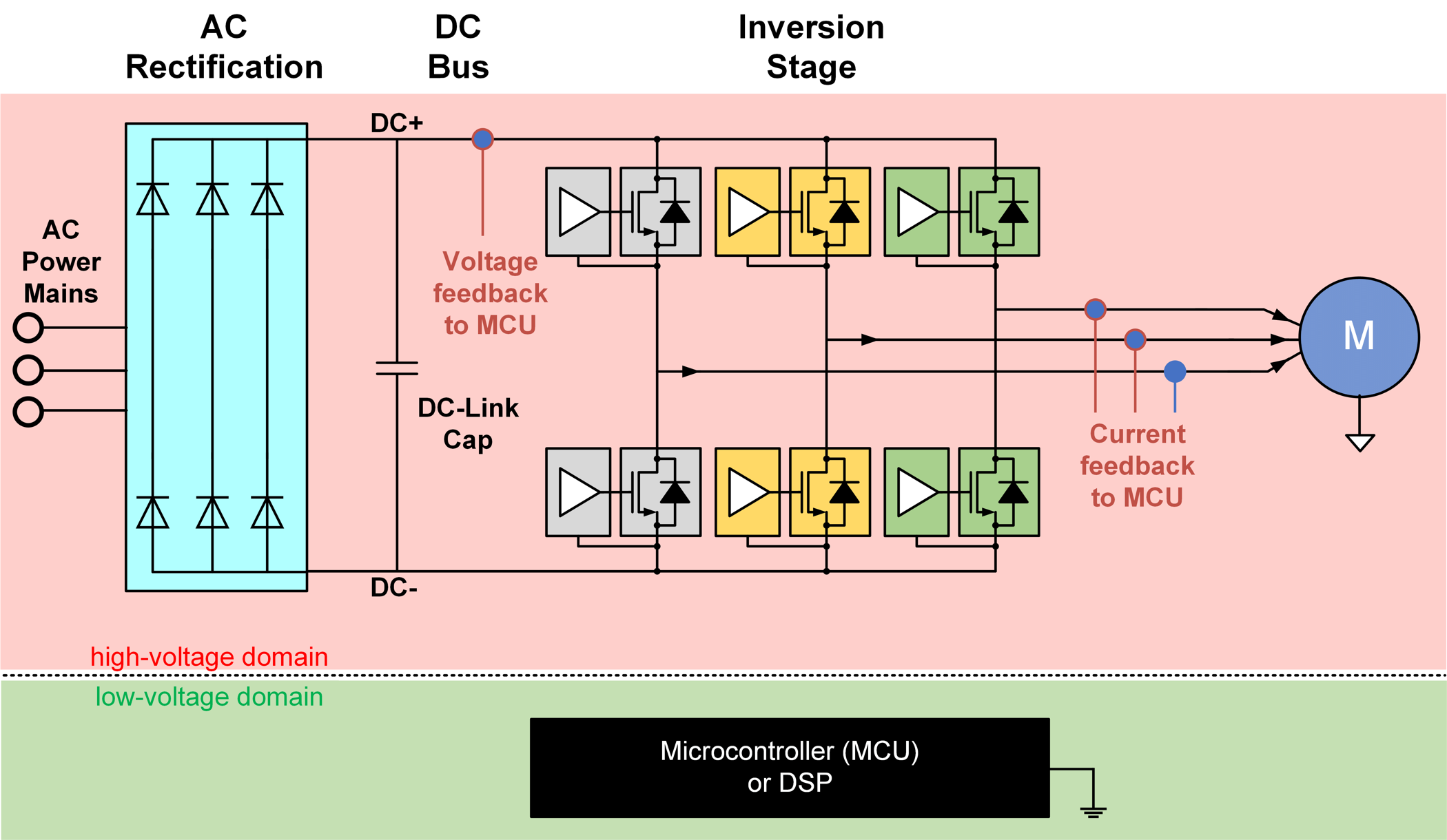
An electric motor-drive system, as shown in Figure 2-1, takes power from the AC mains, rectifies it to a DC voltage, and inverts the DC back to AC with variable magnitude and frequency based on load demand through complex feedback control algorithms.
A motor-drive system typically has two voltage domains: the “high-voltage” domain and the “low-voltage” domain. The microcontroller or digital signal processor, typically on the low-voltage domain, receives feedback signals (voltage, current, temperature, etc.) from the three-phase IGBT power stage and generates pulse-width modulated signals for controlling the power switching transistors and other high-side power circuitry. Such systems demand resilient and reliable galvanic isolation to isolate high-voltage circuits from low-voltage circuits. An isolation architecture enables reliable operation of motor-drive systems, preventing damage to expensive circuitry by breaking the ground loops between the high- and low- voltage circuits and helping protect human operators from high voltages.
Electric motor drives are susceptible to several electrical fault events. As shown in Figure 3-1, a shoot-through fault occurs when the adjacent power switching transistors, 1 and 2, accidentally turn on at the same time. This fault can occur because of several reasons: electromagnetic interference, a malfunction in the microcontroller controlling the switching transistors, or simply worn-out switching transistors. This fault short-circuits the DC-link capacitor and can cause catastrophic failure, resulting in excessive heating, fire or even an explosion. Thus, it is imperative to detect shoot-through faults and take corrective actions such as turning off the power switching transistor very quickly.
As shown in Figure 3-2, a ground fault occurs when the motor cables, motor casing or motor windings are shorted to ground. Such shorts to ground can occur because of dielectric strength degradation in insulation caused by overstress conditions in temperature or voltage over an extended period of time. Old motors and cables are more vulnerable to ground-fault events, which can put human operators at risk for electric shocks. Thus, a ground fault requires detection and corrective actions such as rewinding or replacing the motor.
As shown in Figure 3-3, a phase-to-phase short fault occurs when there is an insulation breakdown in between two windings of the two phases at the stator. These phase-to-phase shorts can occur because of dielectric strength degradation in insulation caused by overstress conditions in temperature or voltage over an extended period of time. This short results in a huge increase in stator current, resulting in potential damage to the IGBTs in the power stage. Old motors and cables are more vulnerable to phase-to-phase shorts. Like ground faults, phase-to-phase faults need detection and corrective actions such as rewinding or replacing the motor.
Overvoltage occurs for several reasons – back-injection from the motor to the DC-link rail during breaking, poor regulation of AC power abnormal circuit loads, wiring errors and insulation failures. Overvoltage can result in voltage overstresses and excessive current that can damage DC-link capacitors and IGBTs, degrade the electrical insulation, and damage or reduce the lifetime of a motor-drive system. It is extremely important to limit the thermal energy through the IGBT by interrupting or reducing shoot-through, ground faults and phase-to-phase shorts, and avoiding transient overvoltage conditions.
Designers must incorporate multiple levels of reliable detection and protection to prevent damage to motor-drive circuits. Power switching transistors such as IGBTs have relatively short withstand times (less than 10 µs) and can quickly overheat and become damaged from excessive currents.
Current-limiting fuses and circuit breakers provide excellent overcurrent protection, but have slow reaction times and require user intervention. They are often the last resort for protection during a failure event.
To detect and quickly protect the motor drive against these fault conditions, one solution senses the current and voltage at critical electrical paths within the motor drive. The measured current and voltage are received by a host microcontroller that controls high-side power circuits such as power switching transistors and circuit breakers. To suppress overcurrents or overvoltage faults, the host microcontroller either turns off or modifies the switching characteristics of power transistors, or trips the circuit breakers.
Figure 4-1 shows the Texas Instruments (TI) AMC23C14 family of low-latency reinforced isolated comparators in short-circuit current, overcurrent, undercurrent, overvoltage, undervoltage and overtemperature fault-detection scenarios. These devices integrate adjustable comparator threshold functions, include a high-side low-dropout regulator for the power supply, and have a response time of sub-0.5 µs in an eight-pin small-outline integrated circuit package.
Next, review the several use cases for AMC23C14 family of isolated comparators in electric motor drives.
Figure 5-1 shows how AMC23C12 can be used for bidirectional in-phase overcurrent detection.
In a fully operational three-phase AC motor-drive system, the sum of three-phase current to the AC motor should be zero, regardless of braking or running conditions (that is, IA + IB + IC = 0).
Calculating the third-phase current in low- to mid-end motor drives from measured current on two phases can help reduce costs. I recommend monitoring the current on the third phase to detect any electrical fault events. While you could place a current sensor on the third phase with an isolated amplifier or isolated modulator, you could also use a reinforced isolated window comparator AMC23C12 for simplicity, cost-effectiveness and solution size. The AMC23C12offers bidirectional overcurrent detection with an integrated window comparator.
As shown in location 1 of Figure 5-1, a shunt resistor produces a voltage drop that the AMC23C12 reinforced window comparator senses. The AMC23C12 has an open-drain output, OUT, which actively pulls low when the input voltage exceeds the pre-defined threshold values of the voltage on the reference pin for the purposes of overcurrent detection. Figure 5-2 shows an overcurrent event output waveform.
For both overcurrent and short-circuit detection, you can use the AMC23C14 dual window comparator.