SLYT820 February 2022 AMC22C11 , AMC22C12 , AMC23C10 , AMC23C11 , AMC23C12 , AMC23C12-Q1 , AMC23C14
- 1Introduction
- 2Introduction to electric motor drives
- 3Understanding fault events in electric motor drives
- 4Achieving reliable detection and protection in electric motor drives
- 5Use case No. 1: Bidirectional in-phase overcurrent detection
- 6Use case No. 2: DC+ overcurrent detection
- 7Use case No. 3: DC– overcurrent or short-circuit detection
- 8Use case No. 4: DC-link (DC+ to DC–) overvoltage and undervoltage detection
- 9Use case No. 5: IGBT module overtemperature detection
2 Introduction to electric motor drives
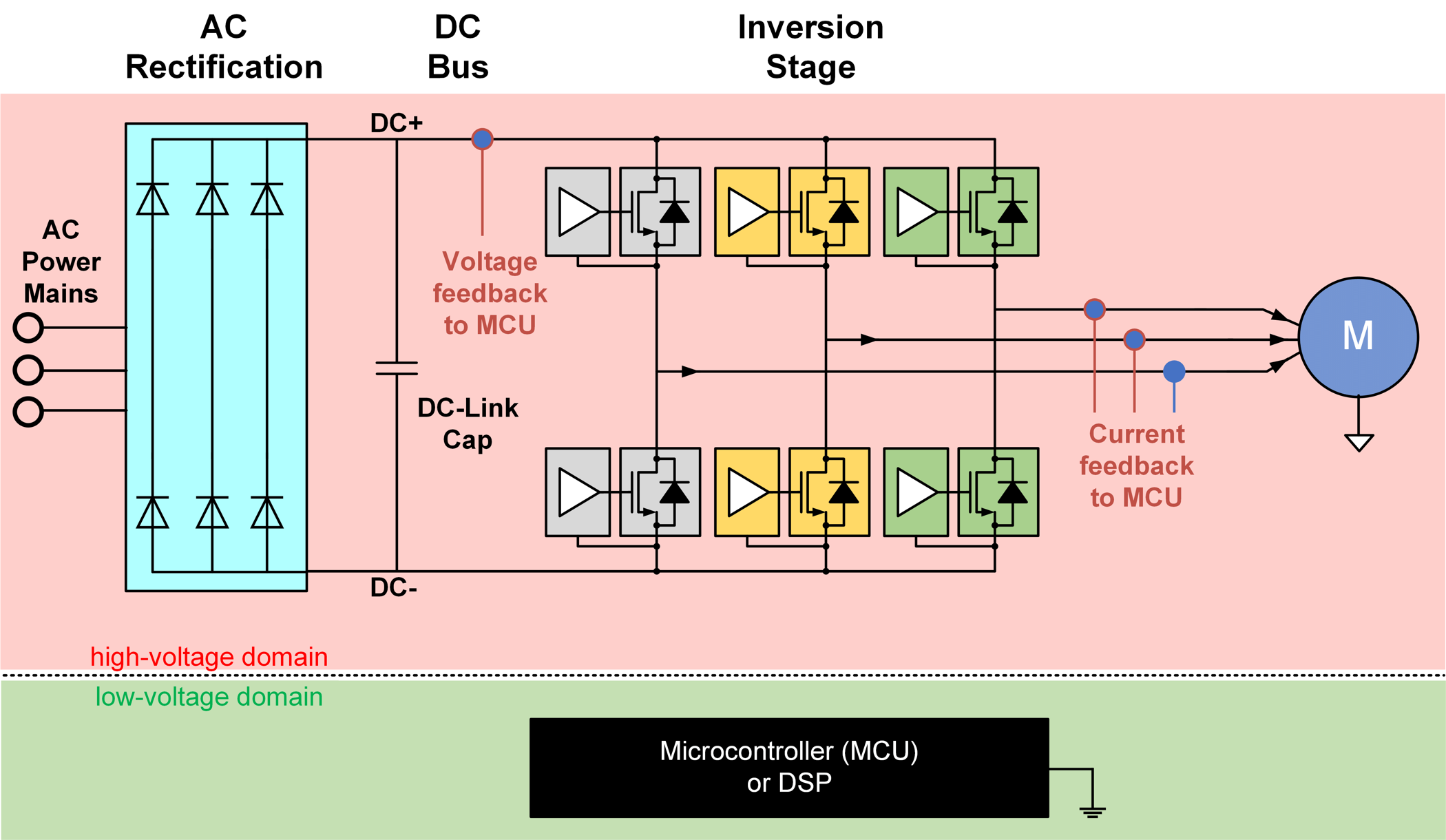
An electric motor-drive system, as shown in Figure 2-1, takes power from the AC mains, rectifies it to a DC voltage, and inverts the DC back to AC with variable magnitude and frequency based on load demand through complex feedback control algorithms.
A motor-drive system typically has two voltage domains: the “high-voltage” domain and the “low-voltage” domain. The microcontroller or digital signal processor, typically on the low-voltage domain, receives feedback signals (voltage, current, temperature, etc.) from the three-phase IGBT power stage and generates pulse-width modulated signals for controlling the power switching transistors and other high-side power circuitry. Such systems demand resilient and reliable galvanic isolation to isolate high-voltage circuits from low-voltage circuits. An isolation architecture enables reliable operation of motor-drive systems, preventing damage to expensive circuitry by breaking the ground loops between the high- and low- voltage circuits and helping protect human operators from high voltages.
 Figure 2-1 AC-input electric motor-drive block diagram