SLYY200A April 2021 – December 2023 LM25149 , LM25149-Q1 , LM5156-Q1 , LM5157-Q1 , LM53635-Q1 , LM60440-Q1 , LM61460-Q1 , LM61495-Q1 , LMQ62440-Q1 , LMR33630-Q1 , LMS3655-Q1 , TPS55165-Q1 , UCC12040 , UCC12050
- 1
- Overview
- At a glance
- What is EMI?
- Conventional methods to reduce EMI in the low- and high-frequency ranges
- Innovations in reducing low-frequency emissions
- Spread spectrum
- Active EMI filtering
- Cancellation windings
- Innovations in reducing high-frequency emissions
- HotRod™ package
- Enhanced HotRod QFN
- Integrated input bypass capacitor
- True slew-rate control
- EMI modeling capabilities
- Low-frequency EMI designs using WEBENCH® design tool
- Conducted and radiated EMI results published in data sheets
- Conclusion
- Keep product categories for low EMI
What is EMI?
In a system that requires electromagnetic compatibility (EMC), components acting as electromagnetic sources are designed to reduce their interference, and components that are susceptible to interference are designed to reduce their susceptibility. When end-equipment manufacturers integrate components from various suppliers, the only way to ensure that the interferers and susceptible circuits can peacefully coexist is through the establishment of a common set of rules, where interference is limited to a certain level, and susceptible circuits are capable of handling that level of interference.
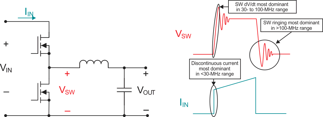
 Figure 1 Example of EMI sources in an
SMPS.
Figure 1 Example of EMI sources in an
SMPS.These rules are established in industry-standard specifications such as Comité International Spécial des Perturbations Radioélectriques (CISPR) 25
for the automotive industry, and CISPR 32 for multimedia equipment. CISPR standards are critical for EMI design, as they will dictate the targeted performance of any EMI mitigation technique. This paper’s focus will be on reducing interference, as the SMPS is typically the electromagnetic interferer. For a comprehensive list of EMI standards, see An overview of conducted EMI specifications for power supplies and An overview of radiated EMI specifications for power supplies.
In addition to knowing the appropriate standard for a given application, it is also important to understand how to measure EMI, as this knowledge will give you insight into reducing EMI. EMI measurements are typically divided into conducted and radiated, which reveal both the method of measurement and how the EMI was generated. Although conducted emissions are typically associated with lower frequencies (<30 MHz) and radiated emissions are typically associated with higher frequencies (>30 MHz), the distinction between the two is not quite so simple, as conducted and radiated frequency ranges do overlap.
Conducted emissions measurements are designed to quantify the EMI generated from a device and returned to its power source. It’s important to reduce these emissions for many applications, as it is common for other sensitive circuits to connect to the same power-supply lines. Reducing conducted EMI is particularly important when dealing with long wire harnesses, which are increasing in number in modern automobiles.
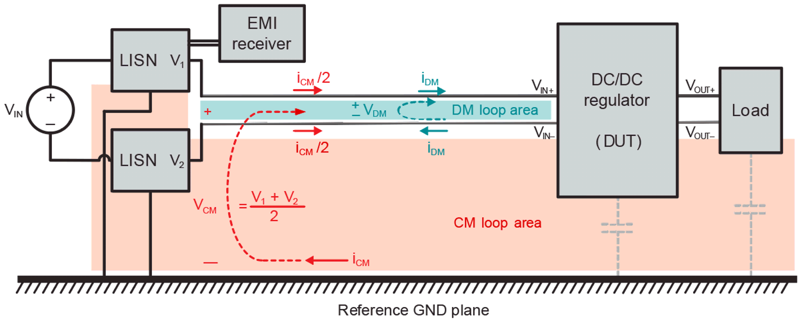
Figure 2 shows a generic test setup for conducted emissions, including a power source, line impedance stabilization network (LISN), EMI receiver, supply wires and a device under test (DUT). The LISN plays a key role, acting as a low-pass filter that ensures the repeatability and comparability of EMI measurements, and providing a precise impedance to the DUT. Figure 2 also illustrates an important subdivision of conducted emissions into common-mode (CM) and differential- mode (DM) currents. DM currents flow between the power-supply line and its return path, and are the dominant factor at lower frequencies. CM currents flow between each of the power lines and ground, and are the dominant factor at higher frequencies.
 Figure 2 Generic test setup for conducted emissions measurements, with DM and CM loops
highlighted in teal and red, respectively.
Figure 2 Generic test setup for conducted emissions measurements, with DM and CM loops
highlighted in teal and red, respectively.Radiated measurements have a setup similar to conducted measurements; the main difference is that the EMI receiver is not connected directly to the LISN but to a nearby antenna. Radiated energy in an SMPS comes from fast transient current loops generating magnetic fields, and fast transient voltage surfaces generating electric fields. Because the same current loops that generate radiated magnetic fields also generate DM conducted emissions, and the same surfaces that generate radiated electric fields also generate CM conducted emissions, many EMI mitigation techniques reduce both conducted and radiated emissions, but may be targeted specifically for one or the other.
In general, lower-frequency emissions are mitigated by using large passive filters, which add board area and cost to the solution. High-frequency emissions present different challenges in terms of measurement, modeling and mitigation, primarily as a result of their parasitic nature. Common mitigation techniques for high-frequency emissions include controlling slew rates and reducing parasitics. Figure 3 summarizes the mitigation techniques contained in this paper, the frequency bands in which they are most beneficial and an example of the frequency ranges covered by the CISPR 25 standard.