SLYY205A March 2021 – October 2022 TPS562211 , TPS562212 , TPS562231 , TPS563211 , TPS563212 , TPS563231 , TPS56339
PFM operation mode
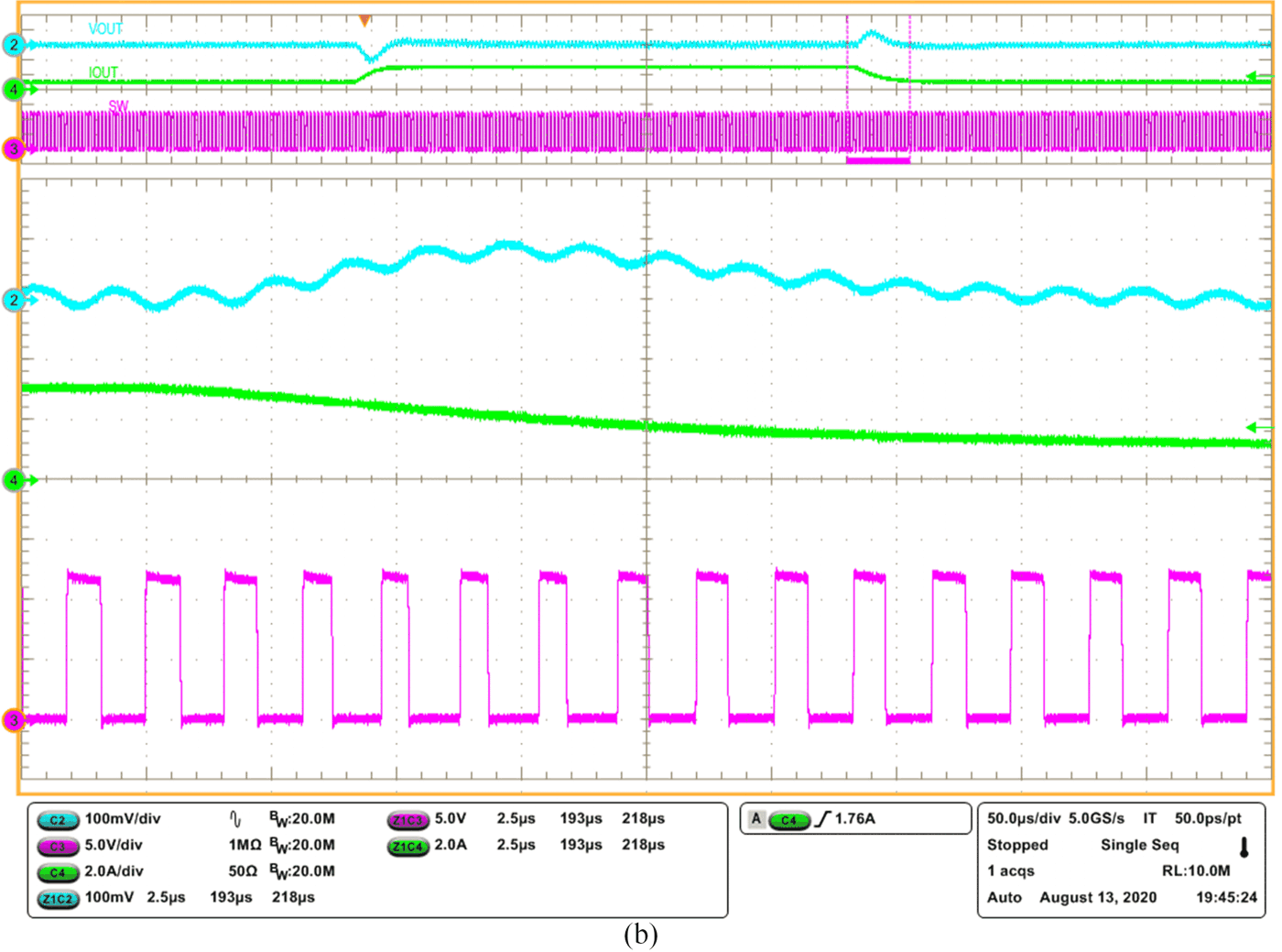
AECM control implements PFM mode to achieve high efficiency under light loads. With a load current decrease, the device enters into discontinuous conduction mode (DCM) from continuous conduction mode (CCM). In both modes, the switching frequency is fixed; the width of the on-pulse (Ton) depends on the load current. Lighter loads have a shorter Ton. AECM has an on-time generator like the D-CAP2 control topology, but that generator is disabled in PWM mode. With the load current further decreasing, the Ton decreases down to the internal clamped on-time, while the AECM device steps into PFM mode with the internal clock blocked and the on-time generator enabled. As shown in Figure 10, the control scheme of PFM mode issimilar to the D-CAP2 control scheme. Figure 11 on the following page shows the transition waveform between PWM mode and PFM mode.

 Figure 11 Duty-cycle changes with the
load current: load step-up (a); load step-down (b).