SNLA433 august 2023 DS320PR1601 , DS320PR410 , DS320PR810 , SN75LVPE5412 , SN75LVPE5421
2.3 PCIe Links with Linear Redrivers
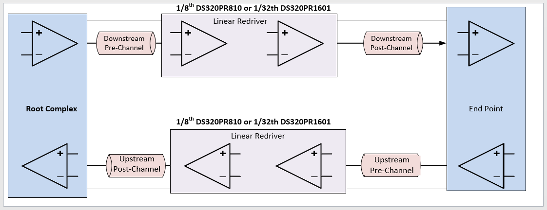
PCI-Express (PCIe) links are typically implemented with 4-lane (x4), 8-lane (x8), and 16-lane (x16) widths. Bidirectional communication between a PCIe root complex (RC) and a PCIe endpoint (EP) is carried over downstream (from RC to EP) and upstream (from EP to RC) channels.
 Figure 2-3 Diagram of a PCIe Link
Transmission media between a PCIe transmitter (TX) and a redriver is a pre-channel, while a channel between a redriver and a PCIe receiver (RX) is a post-channel, indicating the channels' positions relative to the redriver. It is important to note that the pre-channel loss compensation is handled by both PCIe TX equalization and the redriver CTLE.
To check RX EQ compliance, the Phoenix utility is used to do post processing to check that the eye margin conforms to PCIe Gen5 requirements. This post processing involves PCIe Gen5 RX package compensation, behavioral CTLE/DFE, and CDR implementation. This calls for 15 mv vertical eye opening with at least 0.3 UI or 9.375 ps horizontal eye opening. A series of tests—using a BERT with the P9 preset and 800 mVpp amplitude—are done to show redriver ISI or DJ compensation capabilities. In these tests, different pre- and post-channel losses are used.
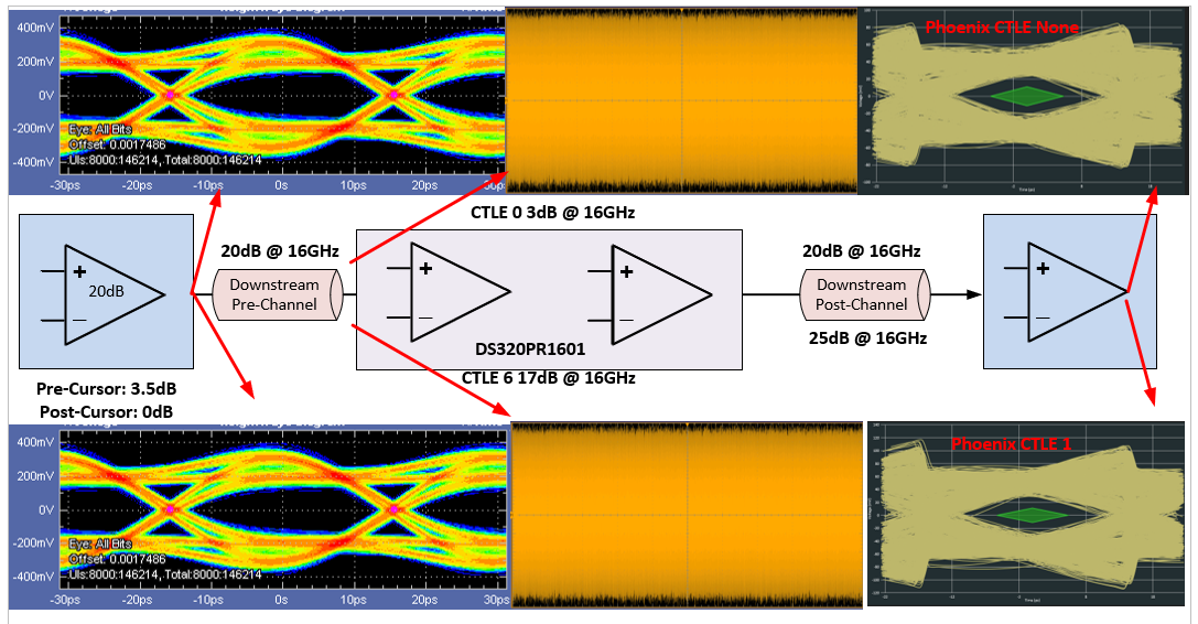
As shown in Figure 2-3, for pre- and post-channel losses of 20 dB, a Gen5 redriver with a CTLE setting of 0 can meet PCI-SIG requirements.
- Pre-channel loss consists of root complex or end point package loss plus PCB trace loss before the device.
- In the second case, we are using the same pre-channel loss, but a higher CTLE (EQ index 6) is used to compensate for the 25 dB post channel loss. The post-channel loss is typically handled by the PCIe receiver through adaptive CTLE, DFE, and negotiated TX equalization. In this case, additional gain provides over-equalization to compensate for the higher 25 dB post channel loss.
 Figure 2-4 PCIe Link Analysis Example
with 20 dB Pre-channel, 20-25 dB Post-channel
Figure 2-4 PCIe Link Analysis Example
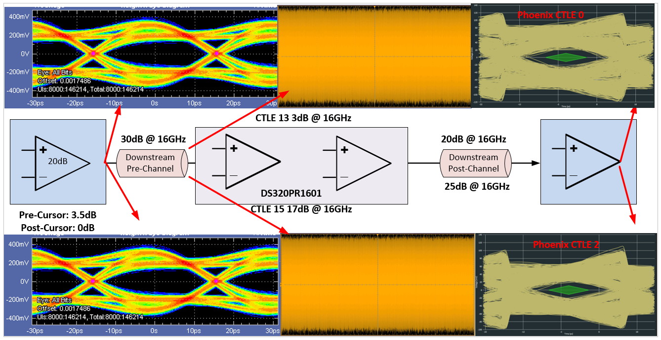
with 20 dB Pre-channel, 20-25 dB Post-channelIn Figure 2-5 and Figure 2-6, we are using a higher pre-channel loss (30 dB) with the same earlier variations of post-channel loss. The redriver mainly compensates for the pre-channel loss and can perform marginal over-compensation to address the increase in pre-channel loss.
 Figure 2-5 PCIe Link Analysis Example
with 30 dB Pre-channel, 20-25 dB Post-channel
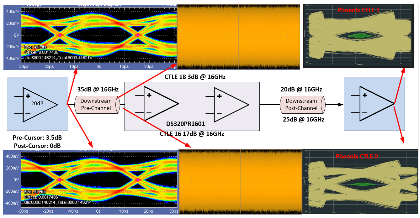
 Figure 2-6 PCIe Link Analysis Example
with 35 dB Pre-channel, 20-25 dB Post-channel
Figure 2-6 PCIe Link Analysis Example
with 35 dB Pre-channel, 20-25 dB Post-channelAs shown, the redriver compensates for the ISI (Inter-Symbol-Interference) on the input due to the transmission media low-pass filtering effects. Either the RC or the EP can compensate for the stressed eye diagram due to other factors: random jitter (RJ), sinusoidal jitter (SJ), reflections caused by impedance discontinuities, skew from mismatched trace lengths, and differential and common mode interferences.