SNVAAB0 August 2024 LM5177 , LM51772
Current Monitoring With Positive and Negative Currents on LM5177x Devices
Introduction
The LM5177, LM51770, and LM51772 are asynchronous buck-boost controllers, which offer current monitoring features with a current sense resistor connected to the ISNSP and ISNSN pins. With the current monitor feature, a control system, such as a uController, can measure the current into the application or from the supply and use this information for additional functions, such as observing and sending warn signals to a host system, or adding an additional control loop.
Depending on the used device, the sensed current will be represented as an easy to measure voltage on the IMONOUT or the CDC pin of the device.
The integrated transconductance amplifier converts the voltage measured on the sense resistor into a proportional current provided on the IMONOUT or CDC pin. With the attached resistor, this signal is transformed into voltage which can be measured with an ADC and processed by a uController.
The integrated transconductance amplifier works in both directions, providing positive and negative current signals. For negative output current a bias voltage need to be supplied on the IMONOUT or CDC pin, instead of a resistor to the AGND. This bias signal can be generated by using the VCC signal, VCC2 signal, or a Reference Voltage, e.g. a uController.
 Figure 1 Block Diagram Showing
Application of the LM51772 to Output the Current Monitor Signal
Figure 1 Block Diagram Showing
Application of the LM51772 to Output the Current Monitor SignalFigure 2 and Figure 3 show the connection of the resistor divider on the current monitor output. In Figure 3 the VCC of the controller is used as reference voltage but RIMON1 can also connect to a reference voltage, such as from the uController, if higher accuracy is required.
 Figure 2 Using CDC on LM51772 to Output Current Monitor Signal
 Figure 3 Using IMONOUT on LM5177 to Output Current Monitor Signal
Calculation of the RIMONx Resistor
The corresponding monitor output voltage is calculated with Equation 1 or Equation 2.
With:
Equation 1 will result in:
Measurement Results
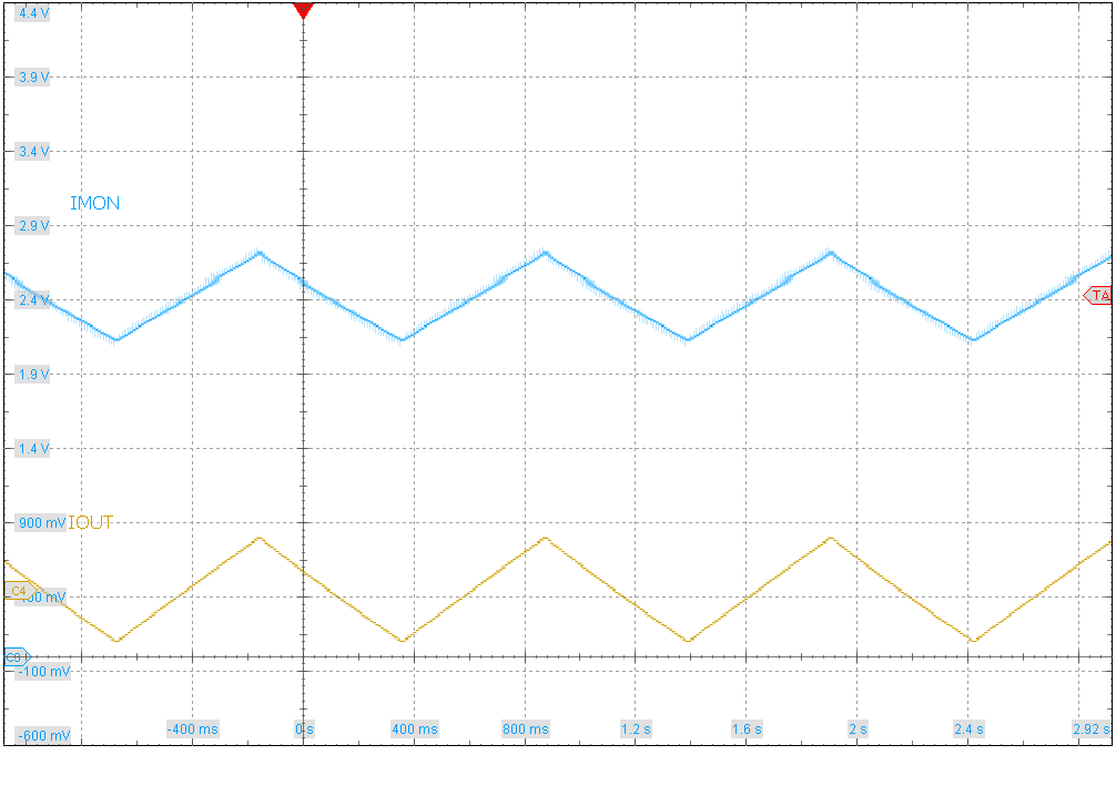
Figure 4 shows the output of the IMONOUT signal related to the positive and negative output current. In this setup a voltage of 2.4V corresponds to 0A output current.
 Figure 4 Scope Plot Showing Output
Current and Current Monitor Signals