SPRABJ8B September 2022 – November 2023 AM2631 , AM2631-Q1 , AM2632 , AM2632-Q1 , AM2634 , AM2634-Q1 , AM263P4 , AM263P4-Q1
9.1.1 Resolver ADC Routing Guidelines
The AM263Px Sensor package includes two Resolver to Digital Converter (RDC) peripherals. A resolver is a type of rotary electrical transformer used for measuring degrees of rotation which is typically attached to an electrical motor. A typical resolver consists of a rotary transformer (exciter winding) and two windings separated by 90 degrees on the stator. An excitation sinusoidal signal is applied to the excitation coil of the resolver and the motor's rotation causes modulated sine and cosine outputs on the sine and cosine sense coils of the resolver. The angle of the modulated sine and cosine signals is directly related to the mechanical angle of the rotor compared to the stator and the speed of the motor rotation.
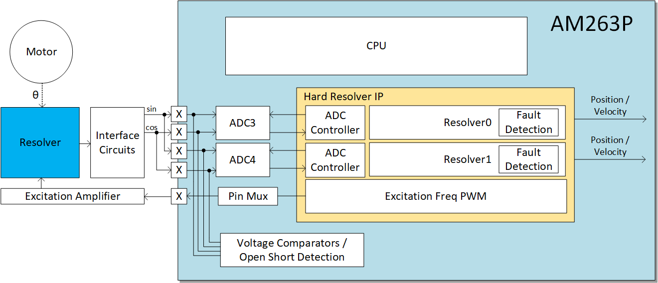
The AM263Px RDCs generate an excitation signal as a PWM which is routed through an excitation amplifier before being applied to the exciter winding on the motor resolver. The resolver sine and cosine outputs are then routed back into the RDC analog inputs, where the RDC IP converts and interprets the signals to determine motor angle and rotational speed. Figure 10-2 shows an example block diagram of a resolver based solution with an AM263P device.
 Figure 9-1 AM263P Resolver ADC System
 The excitation PWM signals from the AM263Px support up to 20KHz and should follow the same guidelines for PCB routing as other similar frequency digital signals. For guidance on routing digital signals, see General Digital Peripheral Routing GuidelinesGeneral Analog Peripheral Routing GuidelinesResolver ADC Routing Guidelines.
The Excitation Amplifier is used to convert the excitation PWM signals to sine waves as inputs to the motor resolver. These signals and the sine and cosine signals output from the resolver to the RDC inputs of the AM263Px should follow the same guidelines for PCB routing as other analog signals. For guidance on routing analog signals, see General Digital Peripheral Routing GuidelinesGeneral Analog Peripheral Routing GuidelinesResolver ADC Routing Guidelines.