SPRACT2 August 2020 – MONTH AM67 , AM67 , AM67A , AM67A , AM68 , AM68 , AM68A , AM68A , AM69 , AM69 , AM69A , AM69A , DRA821U , DRA821U , DRA821U-Q1 , DRA821U-Q1 , DRA829J , DRA829J , DRA829J-Q1 , DRA829J-Q1 , DRA829V , DRA829V , DRA829V-Q1 , DRA829V-Q1 , TDA4AEN-Q1 , TDA4AEN-Q1 , TDA4AH-Q1 , TDA4AH-Q1 , TDA4AL-Q1 , TDA4AL-Q1 , TDA4AP-Q1 , TDA4AP-Q1 , TDA4VE-Q1 , TDA4VE-Q1 , TDA4VEN-Q1 , TDA4VEN-Q1 , TDA4VH-Q1 , TDA4VH-Q1 , TDA4VL-Q1 , TDA4VL-Q1 , TDA4VM , TDA4VM , TDA4VM-Q1 , TDA4VM-Q1 , TDA4VP-Q1 , TDA4VP-Q1
2.2 Temperature Effect on Passing Region
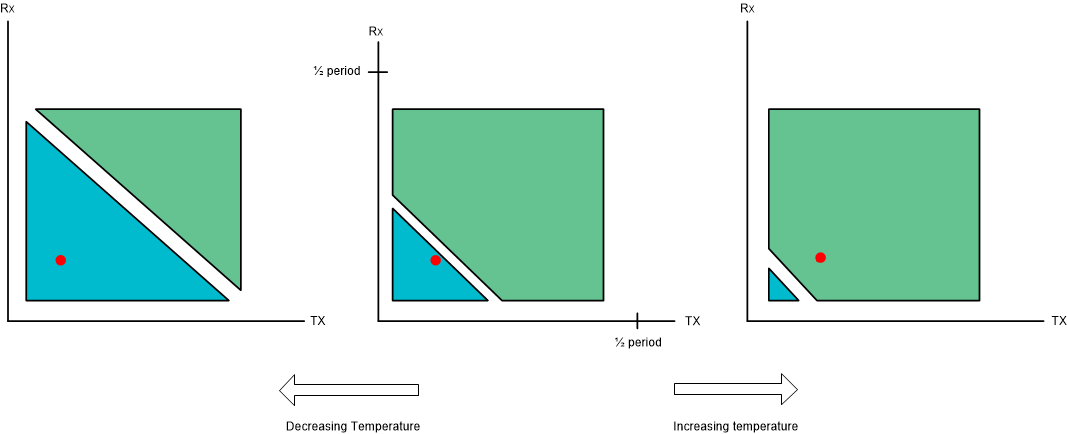
SoC die temperature affects the IO delays, causing changes in the size and location of the passing regions, as shown in Figure 2-2.
 Figure 2-2 Temperature Effect on Passing
Regions
Figure 2-2 Temperature Effect on Passing
RegionsThe boundary between the two passing regions moves with temperature. If that boundary shifts during operation and crosses over the selected tuning point, reads from the OSPI controller will fail to read correct data. Figure 2-2 shows an example of a poorly placed tuning point. The plot on the left shows tuning at low temperature. As temperature increases, IO delays increase, causing the round trip delay to increase. TX and RX PDL values remain the same, and as a result, at high temperatures the sampling point will be in the wrong ref_clk cycle. To account for this, the OSPI tuning algorithm identifies the largest passing region, and selects a TX/RX combination far away from the moving boundary between ref_clk cycles.