SPRACY1 May 2021 F29H850TU , F29H859TU-Q1 , TMS320F2800132 , TMS320F2800133 , TMS320F2800135 , TMS320F2800137 , TMS320F2800152-Q1 , TMS320F2800153-Q1 , TMS320F2800154-Q1 , TMS320F2800155 , TMS320F2800155-Q1 , TMS320F2800156-Q1 , TMS320F2800157 , TMS320F2800157-Q1 , TMS320F280021 , TMS320F280021-Q1 , TMS320F280023 , TMS320F280023-Q1 , TMS320F280023C , TMS320F280025 , TMS320F280025-Q1 , TMS320F280025C , TMS320F280025C-Q1 , TMS320F280033 , TMS320F280034 , TMS320F280034-Q1 , TMS320F280036-Q1 , TMS320F280036C-Q1 , TMS320F280037 , TMS320F280037-Q1 , TMS320F280037C , TMS320F280037C-Q1 , TMS320F280038-Q1 , TMS320F280038C-Q1 , TMS320F280039 , TMS320F280039-Q1 , TMS320F280039C , TMS320F280039C-Q1 , TMS320F280040-Q1 , TMS320F280040C-Q1 , TMS320F280041 , TMS320F280041-Q1 , TMS320F280041C , TMS320F280041C-Q1 , TMS320F280045 , TMS320F280048-Q1 , TMS320F280048C-Q1 , TMS320F280049 , TMS320F280049-Q1 , TMS320F280049C , TMS320F280049C-Q1 , TMS320F28075 , TMS320F28075-Q1 , TMS320F28076 , TMS320F28374D , TMS320F28374S , TMS320F28375D , TMS320F28375S , TMS320F28375S-Q1 , TMS320F28376D , TMS320F28376S , TMS320F28377D , TMS320F28377D-EP , TMS320F28377D-Q1 , TMS320F28377S , TMS320F28377S-Q1 , TMS320F28378D , TMS320F28378S , TMS320F28379D , TMS320F28379D-Q1 , TMS320F28379S , TMS320F28384D , TMS320F28384D-Q1 , TMS320F28384S , TMS320F28384S-Q1 , TMS320F28386D , TMS320F28386D-Q1 , TMS320F28386S , TMS320F28386S-Q1 , TMS320F28388D , TMS320F28388S , TMS320F28P550SJ , TMS320F28P559SJ-Q1 , TMS320F28P650DH , TMS320F28P650DK , TMS320F28P650SH , TMS320F28P650SK , TMS320F28P659DH-Q1 , TMS320F28P659DK-Q1 , TMS320F28P659SH-Q1
2.3 Global Load and One Shot Load Mode
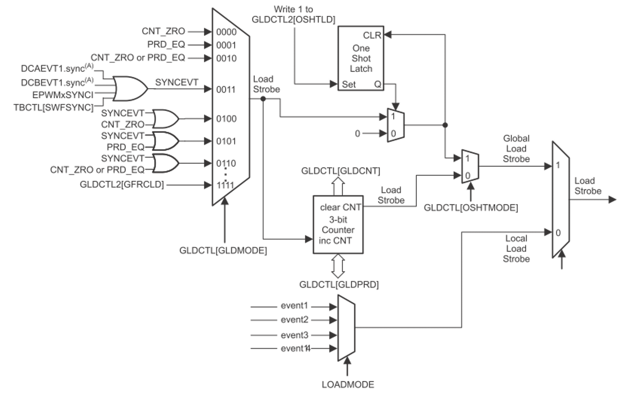
Global load and one shot load mode have been introduced to further address the optimized control for multiple ePWM modules, especially in variable frequency applications. The traditional shadow mode is defined as the local load mode, which is configured individually, while the global load mode applies for all the shadow registers enabled with GLDCFG[REGx]=1. When this feature is enabled (GLDCTL[GLD] = ’1’), the transfer of contents from the shadow register to the active register, occurs at the same event as defined by the configuration bits in Global Shadow to Active Load Control Register (GLDCTL[GLDMODE]. The block diagram is shown in Figure 2-6.
 Figure 2-6 Global Load and One Shot Load
Block Diagram
Figure 2-6 Global Load and One Shot Load
Block DiagramIf the control ISR is asynchronous to the PWM switching frequency, one shot load mode is further required together with global load mode to ensure all the registers in multiple PWM modules are up to date at the selected event.
One shot load mode allows users to ensure the shadow register to active register transfers to occur once, with GLDCTL2[OSHTLD] = ‘1’ under the global load mechanism. In another word, all the global load events are blocked until GLDCTL2[OSHTLD] = ‘1’. Besides, the GLDCTL2 register can also be linked across multiple PWM modules by using EPWMXLINK[GLDCTL2LINK]. Thus, with ePWM linking scheme, when enabling the one shot load mode after all the registers are updated, multiple PWM registers in one or more PWM modules will only take effect in the 1st global load event, and further events will be ignored.