SSZT082 april 2022 BQ79612-Q1 , BQ79614-Q1 , BQ79616-Q1 , BQ79631-Q1 , BQ79731-Q1
As electric vehicles (EVs) become more popular, the challenge for automakers is to reflect true range while making the vehicle more affordable. This translates into making the battery packs lower cost with higher energy densities. Every single watt-hour stored and retrieved from the cells is critical to extend the driving range.
The main function of a battery management system (BMS) is to monitor cell voltages, pack voltages and pack current. In addition, due to the high-voltage design of the BMS, insulation resistance measurement between the high-voltage domain and low-voltage domain is needed to catch defects in the battery structure and protect against hazardous conditions.
 Figure 1 A Traditional BMS Architecture (a); a BMS Architecture with an Intelligent Battery Junction Box (BJB) (b)
Figure 1 presents a typical BMS architecture containing a battery management unit (BMU), cell supervisor unit (CMU) and a battery junction box (BJB). A BMU typically has a microcontroller (MCU), which manages all of the functions within the battery pack. The traditional BJB is a relay box or a switch box with power contactors that connects the entire battery pack to the load inverter, motor or the battery charger.
Figure 1a shows the traditional BMS. There are no active electronics inside of the junction box. All of the measurements in the BJB are measured at the BMU. There are wires connecting the BJB into the analog-to-digital converter (ADC) terminals.
Figure 1b shows the intelligent BJB. There is a dedicated pack monitor inside the box that measures all voltages and currents and passes the information to the MCU using simple twisted-pair communication. It helps eliminating wires and cabling harnesses; and improves voltage and current measurements with lower noise.
Voltage, Temperature and Current Measurement
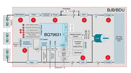
 Figure 2 High-voltage Measurements inside the BJB
- Voltage: The high-voltage is measured using divided-down resistor strings. These voltage measurements monitor the state of high-voltage components in the system.
- Temperature: The temperature measurements monitor the temperature of the shunt resistor so that the MCU can apply compensation, as well as the temperature of the contactors to make sure that they are not stressed beyond the normal operating conditions.
- Current: The current measurements are based on either:
- A shunt resistor - Because the currents in an EV can go up to thousands of amperes, the shunt resistance values are extremely small – in the range of 25 µΩ to 50 µΩ; or
- A Hall-effect sensor – Used to measure the EV current on the high-voltage rail, while still being isolated. Its dynamic range is typically limited, thus there can be multiple sensors in the system to measure the entire range.
Over Current Fault Detection and Protection
Voltage and Current Synchronization
Synchronization Requirements
Remote Device Communication Support
In addition, TI’s BQ79616-Q1 and BQ79718-Q1battery cell monitor families offer accurate cell voltage and temperature measurements as a part of the CSU implementation which enables a complete BMS eco-system.
Additional Resources
- Watch these TI training videos:
- Check out the white paper, Functional Safety Considerations in Battery Management for Vehicle Electrification.