-
How you can optimize SWaP for next-generation satellites with electrical power systems SSZTCX6A April 2023 – February 2025 TPS7H5001-SP , TPS7H5002-SP , TPS7H5003-SP , TPS7H5004-SP , TPS7H5005-SEP , TPS7H5006-SEP , TPS7H5007-SEP , TPS7H5008-SEP , TPS7H6003-SP , TPS7H6005-SEP , TPS7H6013-SP , TPS7H6015-SEP , TPS7H6023-SP , TPS7H6025-SEP
-
How you can optimize SWaP for next-generation satellites with electrical power systems
How you can optimize SWaP for next-generation satellites with electrical power systems
Kurt Eckles

In the satellite industry, dramatic increases in local data processing, support for higher throughput communication links and the rapid adoption of electrical propulsion systems are driving demand for much higher performance electrical power systems (EPSs). The EPS is part of the bus section of a satellite, providing structural support and housing subsystems such as power, thermal management, communication and propulsion. The EPS generates, stores, regulates and distributes power to all other subsystems and payloads onboard the satellite.
The unique challenges and constraints of space missions require optimizing size, weight and power (SWaP). Here are some of the reasons why SWaP is such a big deal in satellite designs:
- Mission requirements: Ever increasing requirements such as data transmission rate, resolution and sensitivity can impact a satellite’s SWaP requirements.
- Launch limitations: Satellites have size constraints, weight constraints and cost-of-launch constraints that can be $1,000s to $10,000s per kilogram based on the intended orbit.
- Power generation: Satellites generally rely on solar panels, and the size and weight of the panels limit the amount of generated power. The power-generation capacity also affects the weight and size of components, like batteries, and functions such as power distribution and thermal management.
- Operational efficiency: SWaP optimization enables satellites to operate more efficiently in space, resulting in better performance and longer mission lifetimes.
Because power is one of the most valuable resources on a satellite, maximizing EPS efficiency can help extend mission lifetimes, reduce mass and volume, and minimize thermal management overhead.
Beyond efficiency, an EPS must also handle a wide range of voltages and currents because of the number of power-supply topologies. Figure 1 shows some of the most common topologies.
 Figure 1 Common power-supply topologies in satellite power architectures
The components and functions, shown in Figure 2, of a typical satellite EPS are:
- Solar panels (or energy generation): Solar panels are the primary power source for most satellites.
- A battery (or energy storage): The battery stores excess power generated by the solar panels during daylight hours, and provides power to the satellite during an eclipse or when the solar panels are not generating enough power.
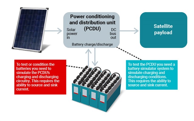
- Power-conditioning unit (PCU): The PCU regulates the electrical output of the solar panels and battery to provide a stable and consistent voltage and current to the rest of the satellite.
- Power-distribution unit (PDU): The PDU distributes power generated by the solar panels and battery to the various subsystems and payloads onboard the satellite.
- Backup power supply: If the primary EPS fails, a backup power supply will help maintain the most essential functions until the restoration of the primary system.
 Figure 2 A typical satellite EPS
Designers can solve their SWaP design challenges in satellite systems by combining pulse-width modulation (PWM) controllers with gate drivers and either silicon MOSFETs or GaN FETs. This approach enables development of optimized power supplies for the different parts of the EPS system.
When developing EPS, designers can select from a diverse range of the voltage and current level radiation-hardened Half-bridge GaN FET gate drivers that scale across the satellite’s entire EPS power tree. Available devices include the TPS7H6003-SP (200V), TPS7H6013-SP (60V), TPS7H6023-SP (22V) (100 krad TID, 75 MeV⋅cm2/mg SEL immune) and radiation-tolerant TPS7H6005-SEP (200V), TPS7H6015-SEP (60V), TPS7H6025-SEP (22V) (50 krad TID, 43 MeV⋅cm2/mg SEL immune). These gate drivers provide design flexibility by supporting a number of different power supply topologies and input formats.
Additionally, designers can also use PWM controllers like radiation-hardened TPS7H5001-SP and radiation-tolerant TPS7H5005-SEP PWM controllers that are designed to support a range of different power-supply implementations.
TI developed the following reference designs to help engineers working with space-grade PWM controllers and GaN FET gate drivers in various power-supply circuits, not only in the EPS, but also on select payload applications:
- Non-isolated high-voltage buck design
- Features a 300W non-isolated synchronous buck topology that supports an input of 50V to 150V with an output of 28YV, using the above mentioned PWM controllers and gate drivers.
- This design is optimized for regulating the highly variable output of 100-V solar panels before the satellite passes the power to the battery storage portion of an EPS subsystem.
- Example TI reference kit: PMP23552
- Isolated full-bridge design
- Features a 100W isolated synchronous hard-switch full-bridge topology that supports an input of 22V to 36V with an output of 5V and uses GaN FETs in the power stage.
- This design is meant to be an example for the power-conditioning and distribution unit (PCDU). With this architecture of devices numerous implementations and output voltage are possible, for example, the zero-voltage-switching (ZVS) full-bridge topology outlined in the article, "Power Tips #134: Don’t switch the hard way; achieve ZVS with a PWM full bridge."
- Example TI reference kit: PMP23200
- Additional resources: User's guide "28-V to 5-V, 10-A Flyback Converter Design With TPS7H5001-SP."
- Non-isolated high-current multiphase buck design
- This design uses PWM controller and gate drivers in a multiphase synchronous buck topology to support an input of 11V to 14V with an output of 0.8 V and again uses GaN FETs in the power stage. The design is dual-phase implementation that is capable of supporting 80A while maintaining acceptable DC and AC tolerance.
- Designers can extend designs to more phases, helping meet design requirements like high current (100A+) and low input voltages (sub-0.8 V) needed to power the core rails of some advanced field-programmable gate arrays, ASICs or multicore processors.
- Example TI reference kit: TIDA-010958
- Additional resources: Application note "12 VIN to 1 VOUT Single Phase Buck Converter Using TPS7H5001-SP Controller."
Conclusion
With power being one of the most valuable resources on a satellite, the EPS architecture can have a significant impact on the overall design. TI’s radiation-validated PWM controller families provide high efficiency and support a wide range of topologies, as well as an architecture that’s deployable in a diverse set of missions and orbits.
Additional resources
- Check out the TI Space Products Guide, Radiation Handbook for Electronics and Spacecraft Circuit Design Handbook.
- Watch our on-demand webinar, Basics of Flyback Power Converter Modeling in SIMPLIS for Satellite Applications.
Trademarks
All trademarks are the property of their respective owners.
IMPORTANT NOTICE AND DISCLAIMER
TI PROVIDES TECHNICAL AND RELIABILITY DATA (INCLUDING DATASHEETS), DESIGN RESOURCES (INCLUDING REFERENCE DESIGNS), APPLICATION OR OTHER DESIGN ADVICE, WEB TOOLS, SAFETY INFORMATION, AND OTHER RESOURCES “AS IS” AND WITH ALL FAULTS, AND DISCLAIMS ALL WARRANTIES, EXPRESS AND IMPLIED, INCLUDING WITHOUT LIMITATION ANY IMPLIED WARRANTIES OF MERCHANTABILITY, FITNESS FOR A PARTICULAR PURPOSE OR NON-INFRINGEMENT OF THIRD PARTY INTELLECTUAL PROPERTY RIGHTS.
These resources are intended for skilled developers designing with TI products. You are solely responsible for (1) selecting the appropriate TI products for your application, (2) designing, validating and testing your application, and (3) ensuring your application meets applicable standards, and any other safety, security, or other requirements. These resources are subject to change without notice. TI grants you permission to use these resources only for development of an application that uses the TI products described in the resource. Other reproduction and display of these resources is prohibited. No license is granted to any other TI intellectual property right or to any third party intellectual property right. TI disclaims responsibility for, and you will fully indemnify TI and its representatives against, any claims, damages, costs, losses, and liabilities arising out of your use of these resources.
TI’s products are provided subject to TI’s Terms of Sale (www.ti.com/legal/termsofsale.html) or other applicable terms available either on ti.com or provided in conjunction with such TI products. TI’s provision of these resources does not expand or otherwise alter TI’s applicable warranties or warranty disclaimers for TI products.
Mailing Address: Texas Instruments, Post Office Box 655303, Dallas, Texas 75265
Copyright © 2025, Texas Instruments Incorporated