TIDUF52 December   2023 MSPM0L1303 , MSPM0L1304 , MSPM0L1305 , MSPM0L1306 , MSPM0L1343 , MSPM0L1344 , MSPM0L1345 , MSPM0L1346


  1.   1
  2.   Description
  3.   Resources
  4.   Features
  5.   Applications
  6.   6
  7. 1System Description
    1. 1.1 Key System Specifications
  8. 2System Overview
    1. 2.1 Block Diagram
    2. 2.2 Design Considerations
      1. 2.2.1 Photoelectric Smoke Detector Background – DC-Based Signal Chain
      2. 2.2.2 Modulation-Based Smoke Detection Signal Chain
      3. 2.2.3 Optical Sensing AFE Design
        1. 2.2.3.1 TIA
        2. 2.2.3.2 BPF
        3. 2.2.3.3 Demodulator and Integrator
        4. 2.2.3.4 LED Driver
      4. 2.2.4 Optical and Mechanical Design
    3. 2.3 Highlighted Products
      1. 2.3.1 MSPM0L1306
      2. 2.3.2 TLV9062S
      3. 2.3.3 TPS7A24
      4. 2.3.4 TS5A623157
      5. 2.3.5 SN74LVC1G66
      6. 2.3.6 HDC2010
  9. 3Hardware, Software, Testing Requirements, and Test Results
    1. 3.1 Hardware Requirements
      1. 3.1.1 Power
      2. 3.1.2 Communication Interface
      3. 3.1.3 Headers
    2. 3.2 Software Requirements
      1. 3.2.1 Getting Started Firmware
      2. 3.2.2 Measurements and Smoke Detection
      3. 3.2.3 Additional Demonstration Functionality
      4. 3.2.4 Smoke Detector GUI
    3. 3.3 Test Setup
      1. 3.3.1 UL217 Smoke Box and Fire Testing Setup
      2. 3.3.2 Ambient Light Testing Setup
      3. 3.3.3 Air-Quality Sensing Test Setup
    4. 3.4 Test Results
      1. 3.4.1 UL217 Testing Results
      2. 3.4.2 Ambient Light Testing Results
      3. 3.4.3 Air-Quality Sensing Test Results
      4. 3.4.4 Power Testing Results
      5. 3.4.5 Fire Room Smoke Testing
  10. 4Design and Documentation Support
    1. 4.1 Design Files
      1. 4.1.1 Schematics
      2. 4.1.2 BOM
      3. 4.1.3 CAD Files
    2. 4.2 Tools and Software
    3. 4.3 Documentation Support
    4. 4.4 Support Resources
    5. 4.5 Trademarks
  11. 5About the Author

Communication Interface

The module also provides the interface for data communication and re-programing. To do this, connect the connector J5 (GND, RXD, TXD, NRST, SWDIO, SWCLK, and BSL) to the J101 (XDS110-ET Debug Probe domain) connector on the LP-MSPM0L1306 LaunchPad Development Kit as Figure 3-1 shows.

The XDS110-ET provides a back-channel UART-over-USB connection with the host, which can be very useful during debugging and for easy communication with a PC. This interface is used by the GUI described in Section 3.2.4 as well for receiving signal chain output data for post-processing on a PC. Connect RXD and TXD for application UART communication.

Connect NRST (Reset signal), SWDIO (serial wire debug data signal), SWCLK (serial wire debug clock signal) and BSL (bootstrap loader signal) for programing and debugging. More details related to those jumpers are found in the MSPM0L1306 LaunchPad Development Kit (LP-MSPM0L1306) user’s guide.
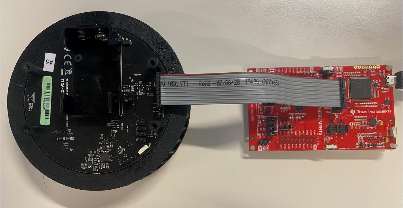
GUID-20231020-SS0I-CPHS-WSZG-M83M02W03SM0-low.jpg Figure 3-1 Connection Between SASI Smoke Detection Module and LP-MSPM0L1306