-
Simplifying Pulse Oximeter Designs With Low-Cost Highly Integrated MSPM0 MCUs SLAAE99 March 2023 MSPM0G1105 , MSPM0G1106 , MSPM0G1107 , MSPM0G1505 , MSPM0G1506 , MSPM0G1507 , MSPM0G3105 , MSPM0G3106 , MSPM0G3107 , MSPM0G3505 , MSPM0G3506 , MSPM0G3507 , MSPM0L1105 , MSPM0L1106 , MSPM0L1303 , MSPM0L1304 , MSPM0L1305 , MSPM0L1306 , MSPM0L1343 , MSPM0L1344 , MSPM0L1345 , MSPM0L1346
-
Simplifying Pulse Oximeter Designs With Low-Cost Highly Integrated MSPM0 MCUs
Simplifying Pulse Oximeter Designs With Low-Cost Highly Integrated MSPM0 MCUs
Introduction
Pulse oximeters are medical instruments for monitoring blood oxygenation. The oxygen level and heart rate measured by the instrument is critical to monitoring patient health and helping medical professionals detect and diagnose medical conditions. Low-cost MSPM0 microcontrollers (MCUs) can help engineers optimize the design and performance of pulse oximeters with MSPM0 Arm® Cortex®-M0+ MCUs like high-performance MSPM0G15xx devices or low-cost MSPM0Lxx devices.
Theory of operation
A pulse oximeter is a noninvasive device that monitors the pulse rate and peripheral oxygen saturation (SpO2 %) of blood.
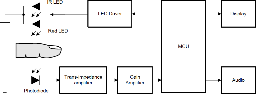
As #FIG_DK1_QF4_HWB shows, when red and IR light emitting diodes (LEDs) are driven alternately through a finger, the unabsorbed light received at the other end of the finger (where a photodiode is used as the sensing element) corresponds to the concentration of Hb and HbO2 in the blood.
 Figure 1-1 Block Diagram of Pulse Oximeter
These measurements include both DC and AC components. The application treats the DC component as the result of absorption by the body tissue and veins and the AC component as the result of absorption by the arteries.
Why are MSPM0 MCUs suitable for pulse oximeter designs?
MCUs in TI’s scalable MSPM0 MCU portfolio feature a M0+ core, with a maximum CPU speed of 32 or 80 MHz. This pin-to-pin compatible portfolio provides memory options from 4KB to 512KB of flash memory with scalable analog integration. With extended analog and interface integration, the MSPM0 portfolio provides low power, high performance, low cost, and reliable options for pulse oximeter designs.
MSPM0 design for pulse oximeter
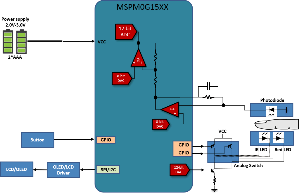
#FIG_NSZ_224_HWB shows a proposed block diagram of an MSPM0G15xx-based pulse oximeter design. The two on-chip zero-drift chopper op-amps (OPA) amplify signals generated by the photodiode. The 8-bit DAC is used as an adjustable bias for the two OPAs. The IR LED and red LED are controlled by the DAC12 to provide different light intensities for different test conditions when taking a reading. An internal timer can be used to trigger the ADC and update the output value of DAC12.
 Figure 1-2 MSPM0G15xx Block Diagram for Pulse Oximeter
Key feature requirements for MCUs in these applications:
- Two on-chip zero-drift chopper op-amps (OPA)
- Internally used 8-bit DAC
- 12-bit DAC
- SPI, I2C, and UART
Software functions on MSPM0:
- IR and red LED control by DAC12 and GPIO
- Bias adjustment for OPAs
- ADC12 sample control
- Sample data process
- Display result on LCD or OLED
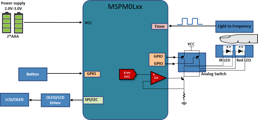
Two options are described below for using MSPM0L series devices in a pulse oximeter design. #FIG_DSP_D24_HWB shows one proposed block diagram of a MSPM0L series application. For this application, two op-amps (OPA) control the LED intensity. The single 8-bit DAC is shared by the two op-amps, so the DAC must be set to different values depending on the currently selected LED. Finally, the light sensor uses a light-to-frequency converter to generate a frequency signal captured by a timer.
 Figure 1-3 Option 1: MSPM0L Series Block Diagram for Pulse Oximeter
Key feature requirements for MCU in these applications:
- On-chip zero-drift chopper op-amps (OPA)
- Internally used 8-bit DAC
- Timer capture
- SPI, I2C, or UART
Software functions on MSPM0:
- IR and Red LED control by OA and GPIO
- Timer capture of the frequency
- Data process
- Display results on an LCD or OLED
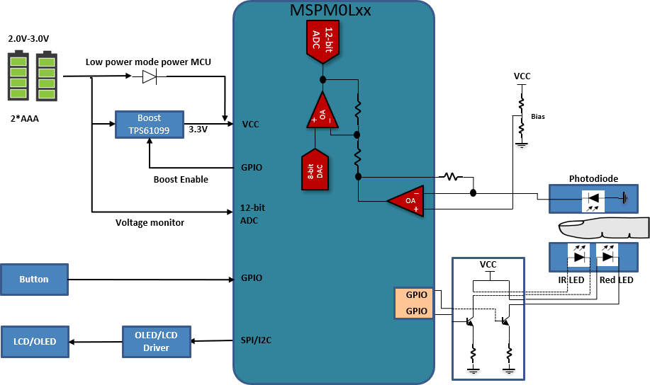
#FIG_OTK_D24_HWB shows the other proposed block diagram of a MSPM0L series application. The two on-chip zero-drift chopper op-amps (OPA) amplify the signals generated by the photodiode. The 8-bit DAC is used as an adjustable bias for the second OPA. The first stage OPA uses an external fixed bias. The IR LED and red LED are controlled directly by GPIOs. To ensure the LED intensity remains consistent even as battery voltage changes over the lifetime of the product, a boost converter is needed.
 Figure 1-4 Option 2: MSPM0L Series Block Diagram for Pulse Oximeter
Key feature requirements for MCUs in these applications:
- Two on-chip zero-drift chopper op-amps (OPA)
- Internally used 8-bit DAC
- SPI, I2C, or UART
Software functions on MSPM0:
- IR and red LEDs controlled by GPIO
- Bias adjust for second stage OPA
- ADC12 sample control
- Sample data process
- Display results on an LCD or OLED
Resources
Order an MSPM0 LaunchPad development kit today to start evaluating MSPM0 for your pulse oximeter. Jump start your pulse oximeter design with MSPM0 code examples and interactive online trainings. The following additional resources are available.