-
Inductive Sensing: Meet the New Multichannel LDCs
Inductive Sensing: Meet the New Multichannel LDCs
Ben Kasemsadeh
If you have been reading my blog series on how to design inductive sensing with the LDC1001 inductance-to-digital converter since we released it , you know how excited I am about the many uses and design opportunities. But until now, design could have been a bit complicated when your system required multiple inductive sensors. That’s why I’m now excited to share that TI has expanded our inductive sensing portfolio to include six 3.3V I2C multichannel devices: the LDC1312, LDC1314, LDC1612, LDC1614 as well as the new LDC2112, LDC2114 and LDC3114-Q1 (see Figure 1).
 Figure 1 TI’s New Inductive Sensing
Solutions
Figure 1 TI’s New Inductive Sensing
SolutionsThe LDC1312 and LDC1314 are 12-bit inductance-to-digital-converters (LDCs), which can be used for applications such as rotational knobs, keypads or flow meters. The LDC1612 and LDC1614 are 28-bit LDCs, which can be used in high-precision applications such as linear encoders or strain gauges.
The LDC2112 and LDC2114 are 12-bit devices that an be used for touch-button applications.
The LDC3114-Q1 is a 24-bit device that can be used for touch-button applications as well as for precise linear position sensing of metal targets for automotive, consumer and industrial applications by allowing access to the raw data representing the inductance value.
Here are some reasons to consider a new LDC device for your next design.
Multichannel Operation
With the dual-channel LDC1312, LDC1612 and LDC2112 devices and the quad-channel LDC1314, LDC1614, LDC2114 and LDC3114-Q1 devices, system design can become much simpler while also improving cost effectiveness. The inherent channel matching from using a multichannel LDC improves system performance in high-precision designs that either employ differential measurements, or use one coil as a reference to reduce the effect of temperature, mechanical tolerances or other system variables.
Sensitivity
The maximum sensing distance changes with coil diameter. As with the LDC1000, the LDC1312 and LDC1314 operate best if the maximum target distance is kept within 50% of the coil diameter. However, the high-resolution of the LDC1612 and LDC1614 can effectively sense targets as far as two coil diameters away from the sensor.
Power Consumption
We significantly improved power consumption of the new LDC family to benefit battery-operated applications. Lowering the supply voltage from 5.0V to 3.3V allowed us to drop power consumption in active mode by 20%, from 8.5 mW to 6.6 mW. Standby-mode power consumption dropped by 91%, from 1.25 mW to 0.11 mW. Additionally, the new LDC family features a pin for shutdown mode, during which the device consumes only 0.2 µA.
In low-sample-rate battery-operated applications, the sleep mode and shutdown mode functions can be used to cycle the LDC. The LDC turns on to perform the conversion and then retunrs to one of the low-power modes. The Inductive Sensing Design Calculator Tool contains a power-consumption estimator for this purpose.
Start Designing
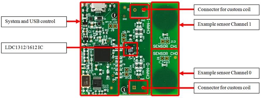
Each of the four multichannel devices has a new evaluation module (EVM) (Figure 2), which is available now. Together with our new multichannel EVM software, you can get started with the new features of our inductance-to-digital converters within minutes. You can also check out the EVM and GUI quick-start videos.
In upcoming posts, I will explain how to configure a multichannel system and explore the possibilities that the increased sensing range of the LDC1612 and LDC1614 offer.
Additional Resources
- Learn more about Inductive Sensing
- Get started with the LDC1614EVM and software
- Check out a TI Design reference design for a touch-on-metal button design using the LDC1614.
- Read more blogs on inductive sensing design, including Should I measure L, RP or both?
IMPORTANT NOTICE AND DISCLAIMER
TI PROVIDES TECHNICAL AND RELIABILITY DATA (INCLUDING DATASHEETS), DESIGN RESOURCES (INCLUDING REFERENCE DESIGNS), APPLICATION OR OTHER DESIGN ADVICE, WEB TOOLS, SAFETY INFORMATION, AND OTHER RESOURCES “AS IS” AND WITH ALL FAULTS, AND DISCLAIMS ALL WARRANTIES, EXPRESS AND IMPLIED, INCLUDING WITHOUT LIMITATION ANY IMPLIED WARRANTIES OF MERCHANTABILITY, FITNESS FOR A PARTICULAR PURPOSE OR NON-INFRINGEMENT OF THIRD PARTY INTELLECTUAL PROPERTY RIGHTS.
These resources are intended for skilled developers designing with TI products. You are solely responsible for (1) selecting the appropriate TI products for your application, (2) designing, validating and testing your application, and (3) ensuring your application meets applicable standards, and any other safety, security, or other requirements. These resources are subject to change without notice. TI grants you permission to use these resources only for development of an application that uses the TI products described in the resource. Other reproduction and display of these resources is prohibited. No license is granted to any other TI intellectual property right or to any third party intellectual property right. TI disclaims responsibility for, and you will fully indemnify TI and its representatives against, any claims, damages, costs, losses, and liabilities arising out of your use of these resources.
TI’s products are provided subject to TI’s Terms of Sale (www.ti.com/legal/termsofsale.html) or other applicable terms available either on ti.com or provided in conjunction with such TI products. TI’s provision of these resources does not expand or otherwise alter TI’s applicable warranties or warranty disclaimers for TI products.
Mailing Address: Texas Instruments, Post Office Box 655303, Dallas, Texas 75265
Copyright © 2023, Texas Instruments Incorporated
