SBAS771D June 2017 – October 2024 AMC1303E0510 , AMC1303E0520 , AMC1303E2510 , AMC1303E2520 , AMC1303M0510 , AMC1303M0520 , AMC1303M2510 , AMC1303M2520
PRODUCTION DATA
- 1
- 1 Features
- 2 Applications
- 3 Description
- 4 Device Comparison Table
- 5 Pin Configuration and Functions
-
6 Specifications
- 6.1 Absolute Maximum Ratings
- 6.2 ESD Ratings
- 6.3 Recommended Operating Conditions
- 6.4 Thermal Information
- 6.5 Power Ratings
- 6.6 Insulation Specifications
- 6.7 Safety-Related Certifications
- 6.8 Safety Limiting Values
- 6.9 Electrical Characteristics: AMC1303x05x
- 6.10 Electrical Characteristics: AMC1303x25x
- 6.11 Switching Characteristics
- 6.12 Timing Diagrams
- 6.13 Insulation Characteristics Curves
- 6.14 Typical Characteristics
- 7 Detailed Description
- 8 Application and Implementation
- 9 Device and Documentation Support
- 10Revision History
- 11Mechanical, Packaging, and Orderable Information
Package Options
Mechanical Data (Package|Pins)
- DWV|8
Thermal pad, mechanical data (Package|Pins)
Orderable Information
8.2.1 Frequency Inverter Application
Isolated ΔΣ modulators are widely used in frequency inverter designs because of the device high ac and dc performance. Frequency inverters are critical parts of industrial motor drives, photovoltaic inverters (string and central inverters), uninterruptible power supplies (UPS), and other industrial applications.
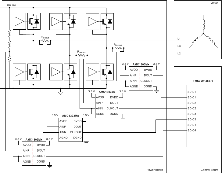
Figure 8-2 shows a simplified schematic of the AMC1303Mx in a typical frequency inverter application as used in industrial motor drives with shunt resistors (RSHUNT) used for current sensing. Depending on the system design, either all three or only two motor phase currents are sensed.
 Figure 8-2 Simplified Diagram of the AMC1303Mx in a Frequency Inverter Application
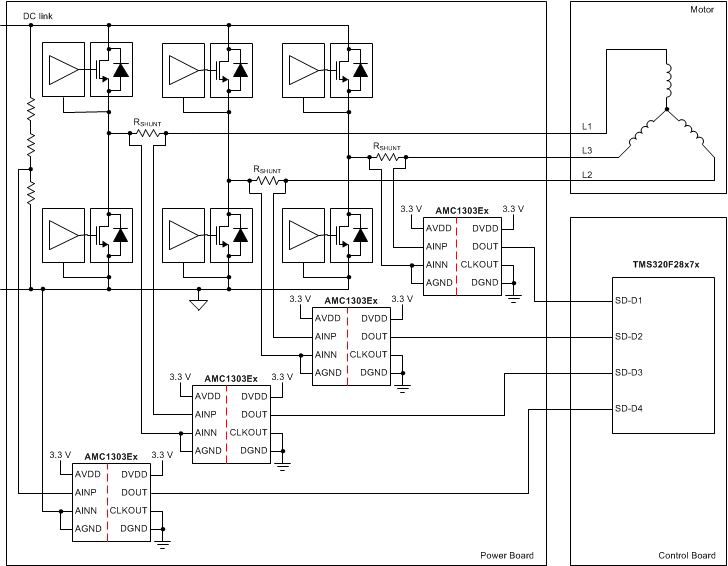
Figure 8-3 shows how the Manchester-coded bitstream output of the AMC1303Ex minimizes the wiring efforts of the connection between the power and the control board. This bitstream output also allows the clock to be generated locally on the power board without the having to adjust the propagation delay time of each DOUT connection to fulfill the setup and hold time requirements of the microcontroller.
 Figure 8-3 Simplified Diagram of the AMC1303Ex in a Frequency Inverter Application
In both examples shown previously, an additional fourth AMC1303 is used to support isolated voltage sensing of the dc link. This high voltage is reduced using a resistive divider and is sensed by the device across a smaller resistor. The value of this resistor degrades the performance of the measurement, as described in the Isolated Voltage Sensing section.