JAJS137I NOVEMBER 2006 – November 2016 DCH010505D , DCH010505S , DCH010512D , DCH010512S , DCH010515D , DCH010515S
PRODUCTION DATA.
- 1 特長
- 2 アプリケーション
- 3 概要
- 4 改訂履歴
- 5 Device Comparison Tables
- 6 Pin Configuration and Functions
- 7 Specifications
- 8 Detailed Description
- 9 Application and Implementation
- 10Power Supply Recommendations
- 11Layout
- 12デバイスおよびドキュメントのサポート
- 13メカニカル、パッケージ、および注文情報
8 Detailed Description
8.1 Overview
The DCH01 series of DC/DC converters are 100% production tested at 3.5 kVDC for 1 second. The isolation test voltage represents an operational isolation to transient voltages and must not be relied upon for safety isolation.
The continuous voltage that can be applied across the DCH01 during normal operation must be < 60 VDC (within SELV limits).
8.1.1 Repeated High-Voltage Isolation Testing
Repeated high-voltage isolation testing can degrade the isolation capability of the DCH01.
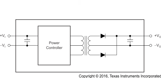
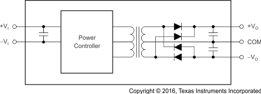
8.2 Functional Block Diagrams
 Figure 20. Single-Output Block Diagram
 Figure 21. Dual-Output Block Diagram
8.3 Feature Description
8.3.1 Isolation
Underwriters Laboratories (UL)™ defines several classes of isolation that are used in modern power supplies.
Safety extra low voltage (SELV) is defined by UL (UL1950 E199929) as a secondary circuit which is so designated and protected that under normal and single fault conditions the voltage between any two accessible parts, or between an accessible part and the equipment earthing terminal for operational isolation does not exceed steady state 42-V peak or 60 VDC for more than 1 second.
8.3.1.1 Operation or Functional Isolation
Operational or functional isolation is defined by the use of a high-potential (hipot) test only. Typically, this isolation is defined as the use of insulated wire in the construction of the transformer as the primary isolation barrier. The hipot one-second duration test (dielectric voltage, withstand test) is a production test used to verify that the isolation barrier is functioning. Products with operational isolation must never be used as an element in a safety-isolation system.
8.3.1.2 Basic or Enhanced Isolation
Basic or enhanced isolation is defined by specified creepage and clearance limits between the primary and secondary circuits of the power supply. Basic isolation is the use of an isolation barrier in addition to the insulated wire in the construction of the transformer. Input and output circuits must also be physically separated by specified distances.
8.3.1.3 Continuous Voltage
For a device that has no specific safety agency approvals (operational isolation), the continuous voltage that can be applied across the part in normal operation is less than 42.4 VRMS or 60 VDC. Ensure that both input and output voltages maintain normal SELV limits. The isolation test voltage represents a measure of immunity to transient voltages.
WARNING
Do not use the device as an element of a safety isolation system when SELV is exceeded.
If the device is expected to function correctly with more than 42.4 VRMS or 60 VDC applied continuously across the isolation barrier, then the circuitry on both sides of the barrier must be regarded as operating at an unsafe voltage. Further isolation or insulation systems must form a barrier between these circuits and any user-accessible circuitry according to safety standard requirements.
8.3.1.4 Isolation Voltage
Hipot test, flash-tested, withstand voltage, proof voltage, dielectric withstand voltage, and isolation test voltage are all terms that relate to the same thing: a test voltage applied for a specified time across a component designed to provide electrical isolation to verify the integrity of that isolation. TI’s DCH01 series of dc-dc converters are all 100% production tested at 3.5 kVDC for 1 second.
8.3.1.5 Repeated High-Voltage Isolation Testing
Repeated high-voltage isolation testing of a barrier component can degrade the isolation capability, depending on materials, construction, and environment. The DCH01 series of dc-dc converters have toroidal, enameled, wire isolation transformers with no additional insulation between the primary and secondary windings. While a device can be expected to withstand several times the stated test voltage, the isolation capability depends on the wire insulation. Any material, including this enamel (typically polyurethane), is susceptible to eventual chemical degradation when subject to very-high applied voltages. Therefore, strictly limit the number of high-voltage tests and repeated high-voltage isolation testing. However, if it is absolutely required, reduce the voltage by 20% from specified test voltage with a duration limit of 1 second per test.