-
UCCx813-x 低消費電力エコノミーBiCMOS電流モードPWM
- 1 特長
- 2 アプリケーション
- 3 概要
- 4 改訂履歴
- 5 Device Comparison Table
- 6 Pin Configuration and Functions
- 7 Specifications
-
8 Detailed Description
- 8.1 Overview
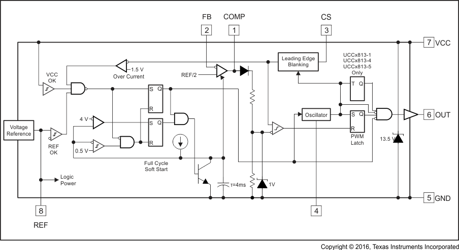
- 8.2 Functional Block Diagram
- 8.3
Feature Description
- 8.3.1 Detailed Pin Descriptions
- 8.3.2 Undervoltage Lockout (UVLO)
- 8.3.3 Self-Biasing, Active Low Output
- 8.3.4 Reference Voltage
- 8.3.5 Oscillator
- 8.3.6 Synchronization
- 8.3.7 PWM Generator
- 8.3.8 Minimum Off-Time Adjustment (Dead-Time Control)
- 8.3.9 Leading Edge Blanking
- 8.3.10 Minimum Pulse Width
- 8.3.11 Current Limiting
- 8.3.12 Overcurrent Protection and Full-Cycle Restart
- 8.3.13 Soft Start
- 8.3.14 Slope Compensation
- 8.4 Device Functional Modes
-
9 Application and Implementation
- 9.1 Application Information
- 9.2
Typical Application
- 9.2.1 Design Requirements
- 9.2.2
Detailed Design Procedure
- 9.2.2.1 Bulk Capacitor Calculation
- 9.2.2.2 Transformer Design
- 9.2.2.3 MOSFET and Output Diode Selection
- 9.2.2.4 Output Capacitor Calculation
- 9.2.2.5 Current Sensing Network
- 9.2.2.6 Gate Drive Resistor
- 9.2.2.7 REF Bypass Capacitor
- 9.2.2.8 RT and CT
- 9.2.2.9 Start-Up Circuit
- 9.2.2.10 Voltage Feedback Compensation Procedure
- 9.2.3 Application Curves
- 10Power Supply Recommendations
- 11Layout
- 12デバイスおよびドキュメントのサポート
- 13メカニカル、パッケージ、および注文情報
- 重要なお知らせ
パッケージ・オプション
デバイスごとのパッケージ図は、PDF版データシートをご参照ください。
メカニカル・データ(パッケージ|ピン)
- D|8
- PW|8
サーマルパッド・メカニカル・データ
発注情報
DATA SHEET
UCCx813-x 低消費電力エコノミーBiCMOS電流モードPWM
このリソースの元の言語は英語です。 翻訳は概要を便宜的に提供するもので、自動化ツール (機械翻訳) を使用していることがあり、TI では翻訳の正確性および妥当性につきましては一切保証いたしません。 実際の設計などの前には、ti.com で必ず最新の英語版をご参照くださいますようお願いいたします。
1 特長
- 起動時消費電流: 100µA (標準値)
- 動作時消費電流: 500µA (標準値)
- 1MHzでの動作
- 内部的なソフトスタート
- 内部的なフォルト・ソフトスタート
- 電流センス信号の内部リーディングエッジ・ブランキング機能
- 1Aのトーテムポール出力
- 電流センスからゲート・ドライブ出力への標準応答時間: 70ns
- 基準電圧の許容誤差: 1.5%
- UCC3802、UC3842、UC3842Aデバイス・ファミリと同じピン配置
2 アプリケーション
- スイッチ・モード電源 (SMPS)
- DC/DCコンバータ
- 電源モジュール
- 産業用PSU
- バッテリ駆動のPSU
3 概要
UCC3813-xデバイス・ファミリは、高速で低消費電力の集積回路で、オフラインおよびDC/DC固定周波数電流モードのスイッチング電源を最小の部品数で設計するため必要な、すべての制御および駆動部品が含まれています。
これらのデバイスは、UC384xデバイス・ファミリとピン構成が同じで、内部的なフルサイクル・ソフトスタートや、電流センス入力の内部リーディングエッジ・ブランキングなどの追加機能も提供します。
UCC3813-xデバイス・ファミリは、各種のパッケージ・オプション、温度範囲オプション、最大デューティ・サイクルの選択、クリティカル電圧レベルの選択が使用可能です。UCC3813-3やUCC3813-5など基準電圧の低いデバイスは、バッテリで動作するシステムに最適です。これに対して、UCC3813-2およびUCC3813-4デバイスは基準電圧とUVLOヒステリシスが高く、オフライン電源での使用に理想的です。
UCC2813-xデバイス・シリーズは-40℃~85℃、UCC3813-xデバイス・シリーズは0℃~70℃での動作が規定されています。
製品情報(1)
| 型番 | パッケージ | 本体サイズ(公称) |
|---|---|---|
| UCC2813-x、 UCC3813-x |
PDIP (8) | 6.35mm×9.81mm |
| SOIC (8) | 3.91mm×4.90mm | |
| TSSOP (8) | 4.40mm×3.00mm |
- 提供されているすべてのパッケージについては、データシートの末尾にある注文情報を参照してください。
ブロック図

4 改訂履歴
Changes from D Revision (May 2013) to E Revision
- Added 「ESD定格」表、「機能説明」セクション、「デバイスの機能モード」セクション、「アプリケーションと実装」セクション、「電源に関する推奨事項」セクション、「レイアウト」セクション、「デバイスおよびドキュメントのサポート」セクション、「メカニカル、パッケージ、および注文情報」セクションGo
Changes from C Revision (August 2010) to D Revision
- Added temperature range table note to second part of ordering information table for clarity in new datasheet formatGo
- Added TI's general Absolute Maximum Ratings table note to end of ABSOLUTE MAXIMUM RATINGS tableGo
- Added Thermal Information Table.Go
- Added UCCX813-3 to Total variation test condition line containing UCCx813-5 in ELECTRICAL CHARACTERISTICS tableGo
- Changed part numbers in Dead Time vs CT, RT = 100 k graph in APPLICATION INFORMATIONGo
- Changed layout from Unitrode Products datasheet to TI datasheetGo
Changes from B Revision (April 2008) to C Revision
5 Device Comparison Table
| PART NUMBER(1) | MAXIMUM DUTY CYCLE | REFERENCE VOLTAGE | TURNON THRESHOLD | TURNOFF THRESHOLD | UNIT |
|---|---|---|---|---|---|
| UCCx813-0 | 100% | 5 | 7.2 | 6.9 | V |
| UCCx813-1 | 50% | 5 | 9.4 | 7.4 | V |
| UCCx813-2 | 100% | 5 | 12.5 | 8.3 | V |
| UCCx813-3 | 100% | 4 | 4.1 | 3.6 | V |
| UCCx813-4 | 50% | 5 | 12.5 | 8.3 | V |
| UCCx813-5 | 50% | 4 | 4.1 | 3.6 | V |
6 Pin Configuration and Functions
N and D Packages
8-Pin PDIP and SOIC
Top View
PW Package
8-Pin TSSOP
Top View
Pin Functions
| PIN | I/O | DESCRIPTION | |
|---|---|---|---|
| NAME | NO. | ||
| COMP | 1 | O | COMP is the output of the error amplifier and the input of the PWM comparator. Feedback loop compensation is applied between this pin and the FB pin. |
| CS | 3 | I | CS is the input to the current-sense comparators: the PWM comparator and the overcurrent comparator. |
| FB | 2 | I | FB is the inverting input of the error amplifier. |
| GND | 5 | — | GND is the reference ground and power ground for all functions of this device. |
| OUT | 6 | O | OUT is the output of a high-current power driver capable of driving the gate of a power MOSFET. |
| RC | 4 | I | RC is the oscillator timing programming pin. An external resistor and capacitor are applied to this input to program the switching frequency and maximum duty-cycle. |
| REF | 8 | O | REF is the voltage reference for the error amplifier and many other functions, and is the bias source for logic functions of this device. |
| VCC | 7 | I | VCC is the bias-power input for this device. In normal operation, VCC is connected to a voltage source through a current-limiting resistor. |