SCDA046A January 2024 – July 2024 TMUX7308F , TMUX7309F , TMUX7348F , TMUX7349F , TMUX7411F , TMUX7412F , TMUX7413F , TMUX7436F , TMUX7462F
1 Fault Protected Multiplexer Operation in System and Requirements for EFT Burst Testing
TI has created fault protected multiplexers which have an integrated feature called over-voltage protection (OVP). The OVP feature of these multiplexers are designed to block input signals outside the range of the positive or negative power supply of the mux. For example, looking at Figure 1-1 let us assume we have a PLC system where the inputs are 24V and the power supply of the multiplexer are ±15V. In this example, the OVP feature of the TMUX7308F activates and disconnects the source input from passing the signal to protect the downstream components in a PLC system.
 Figure 1-1 Typical Application of Fault Protected Multiplexer in PLC System
This same OVP feature can also be used to block EFT burst signals that strike communication lines between analog input and output modules in a factory automation environment. While the immediate protection of components in factory automation communication is important, the other significant detail is the need for fast recovery of communication lines during an EFT burst event. TI’s Fault Protected multiplexers’ fast recovery time (trecover), allows this family of devices to reconnect the analog signal line faster than the time between EFT burst pulses (toff). This maintains that the switch can quickly reconnect PLC modules allowing for accurate communication and minimal signal attenuation during an EFT burst event.
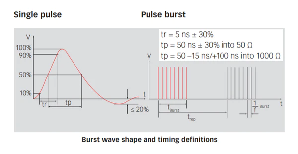
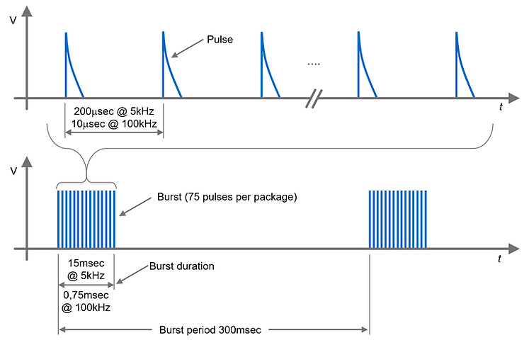
Typical characteristics of EFT burst testing including peak voltage amplitudes, test levels, burst wave shape and timing definitions, and testing repetition times are shown in the figures below (Table 1-1, Figure 1-2, and Figure 1-3).
| Peak Amplitude | ||||
|---|---|---|---|---|
| Power Supply Port | I/O, Signal, Data & Control Lines | |||
| Level | VCC (kV) | ISC (A) | VCC (kV) |
ISC (A) |
|
1 |
0.5 |
10 |
0.25 |
5 |
|
2 |
1 |
20 |
0.5 |
10 |
|
3 |
2 |
40 |
1 |
20 |
|
4 |
4 |
80 |
2 |
40 |
The EFT pulse waveform is defined as and categorized by:
- tr (rise time) = 5ns
- tp (pulse duration) = 50ns
 Figure 1-2 Burst Wave Shape and Timing Definitions
These short pulses are repeated 75 time with a time (trep) and from a specified burst package.
 Figure 1-3 Test Repetition Times
The standard offers two repetition times, 200us (100kHz) or 10us (5kHz) within the burst packet. Each package contains 75 pulses. The resulting burst package duration is 15ms or 750us. Burst packages then repeat every 300ms. With this information, the equivalent duty cycle for both EFT burst repetition times is 0.00125%.
For EFT burst immunity testing the following four criteria are defined:
- Performance Criteria A – Performance within specification limits
- Performance Criteria B – Temporary degradation which is self-recoverable
- Performance Criteria C – Temporary degradation which requires operator intervention
- Performance Criteria D – Loss of function which is not recoverable
PLC systems must at a minimum fulfill Criteria B. Failure to meet this baseline can lead to system operators having to shut down and reset to recover acceptable PLC performance. In worst-case scenarios where no protection switch is used, operators have to completely replace permanently damaged components. To fulfill Criteria B, the signal link must not drop but can be degraded in value. For example, a voltage of 10V can be impacted and voltage can degrade by a typical industry standard percentage of 10%, but the signaling must not be lost and the link must not discharge. System self-recoverability maintains that the signal link does not drop during an EFT burst and only lead to temporary degradation. This is the requirement for Criteria B performance.