SLAAED3A October 2023 – May 2024 TAA5212 , TAA5242 , TAC5111 , TAC5112 , TAC5142 , TAC5211 , TAC5212 , TAC5242
2 Analog Input Configuration
Table 2-1 provides a summary of the different input configurations for IN1 in this application note, the same applies to IN2 input with the register channel change to 2.
Table 2-1 IN1 Input Configuration and Input
Swing
| Input Pin | Input Mode | Topology | Input Swing |
|---|---|---|---|
| IN1P-IN1M | LINE-IN Differential, AC-coupled | 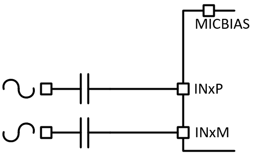 |
2 Vrms |
| IN1P | LINE-IN Single-Ended, AC-coupled | 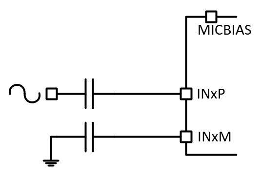 |
1 Vrms |
| IN1P | LINE-IN Single-Ended Mux IN1P, AC-coupled | 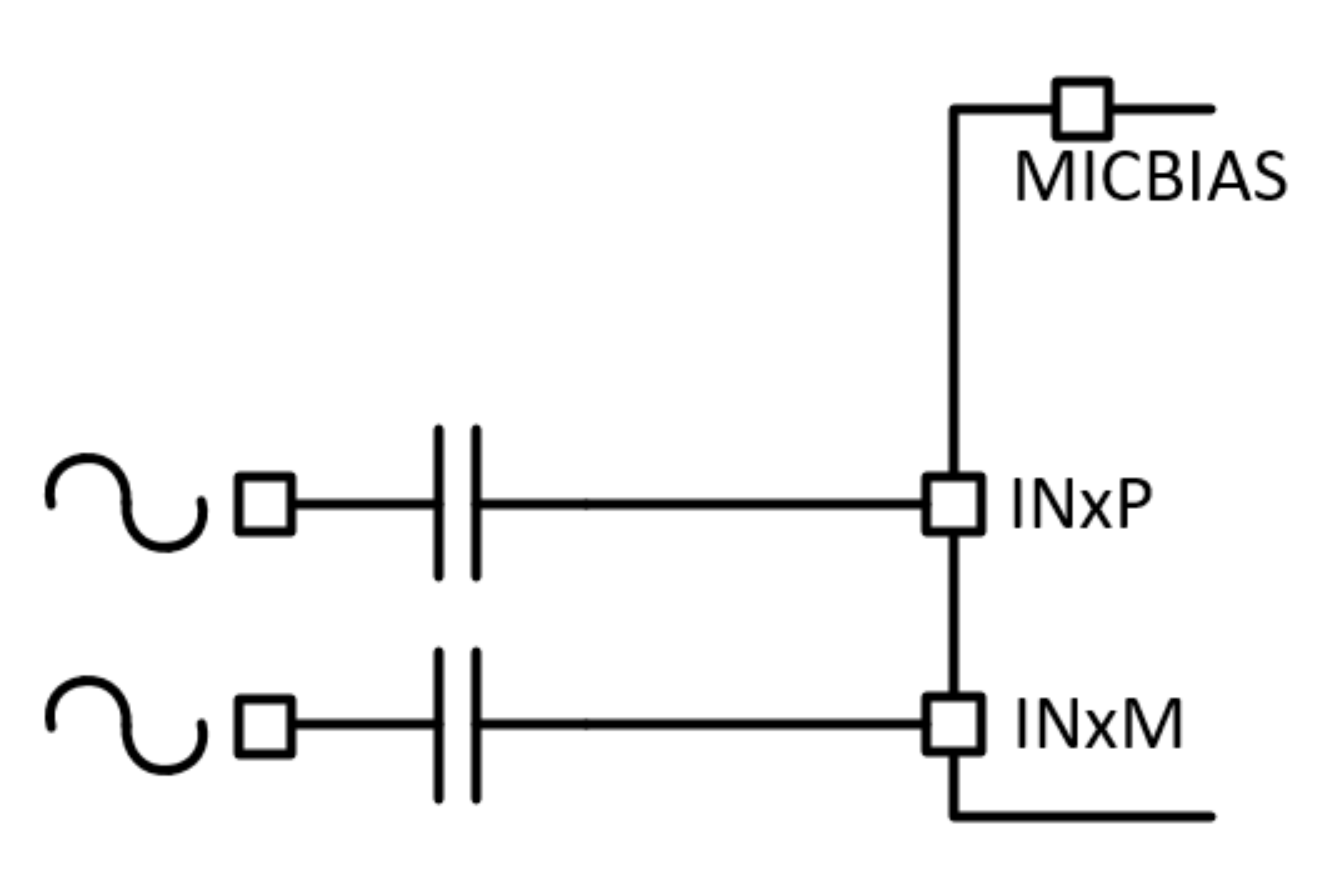 |
1 Vrms |
| IN1M | LINE-IN Single-Ended Mux IN1M, AC-coupled | 1 Vrms | |
| IN1P-IN1M | LINE-IN Differential, DC-coupled | 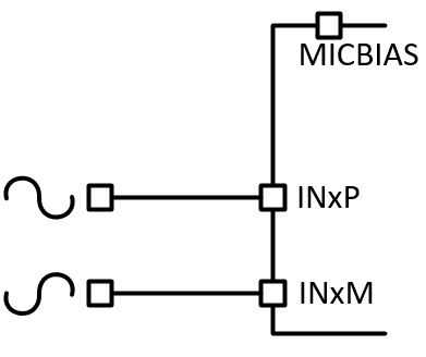 |
4 Vrms |
| IN1P | LINE-IN Single-ended, DC-coupled | 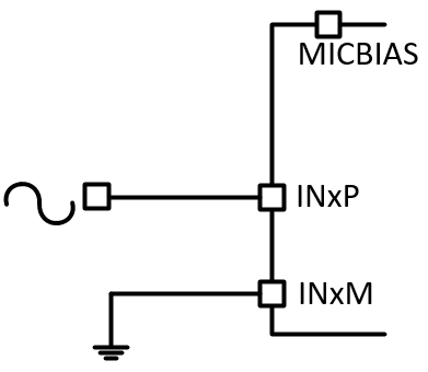 |
2 Vrms |
| IN1P | LINE-IN Single-ended Mux IN1P, DC-coupled | 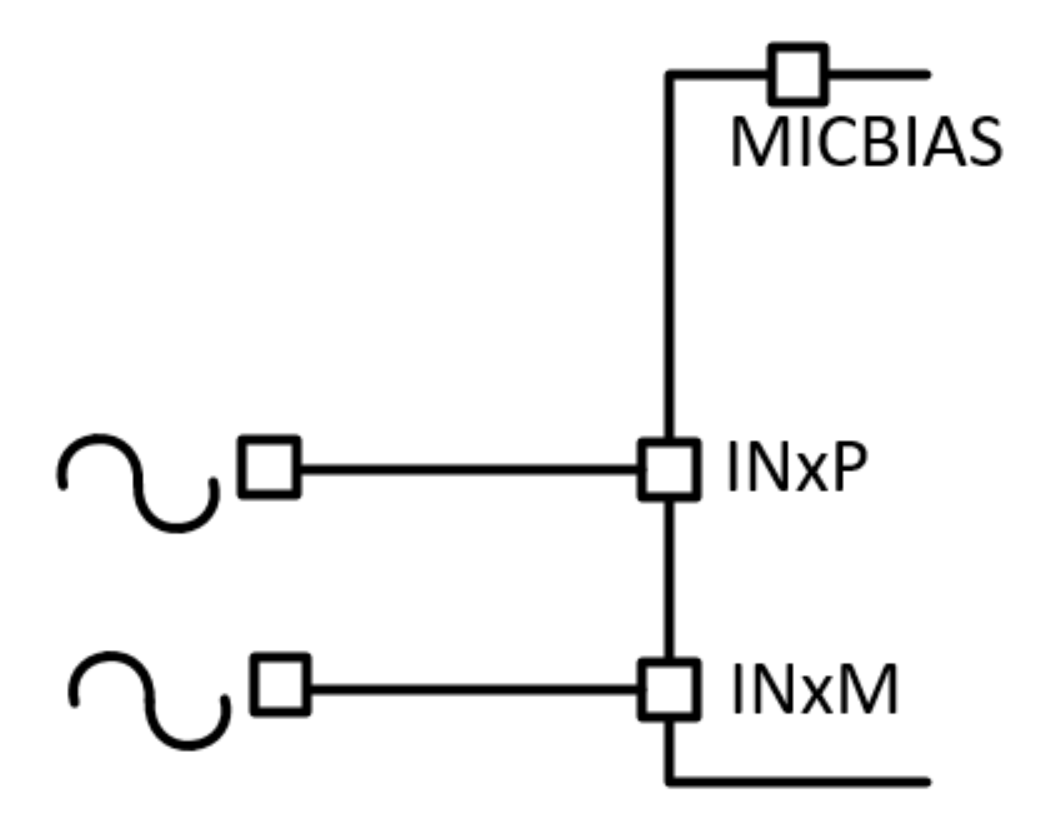 |
2 Vrms |
| IN1M | LINE-IN Single-ended Mux IN1M, DC-coupled | 2 Vrms |
For each of the test, audio signal is provided from APx500 analog balance or unbalanced output with input level referenced to the full-scale swing of the device configuration for example 0 dBrG is referenced to 2 Vrms single ended swing or 4 Vrms differential input swing in DC-Coupled configuration.