SLAAEI9 December 2023 MSPM0C1103 , MSPM0C1103-Q1 , MSPM0C1104 , MSPM0C1104-Q1 , MSPM0G1105 , MSPM0G1106 , MSPM0G1107 , MSPM0G1505 , MSPM0G1506 , MSPM0G1507 , MSPM0G3105 , MSPM0G3105-Q1 , MSPM0G3106 , MSPM0G3106-Q1 , MSPM0G3107 , MSPM0G3107-Q1 , MSPM0G3505 , MSPM0G3505-Q1 , MSPM0G3506 , MSPM0G3506-Q1 , MSPM0G3507 , MSPM0G3507-Q1 , MSPM0L1105 , MSPM0L1106 , MSPM0L1228
- 1
- Abstract
- Trademarks
- 1MSPM0 Portfolio Overview
-
2Ecosystem And Migration
- 2.1 Ecosystem Comparison
- 2.2 Migration Process
- 2.3 Example
- 3Core Architecture Comparison
- 4Digital Peripheral Comparison
- 5Analog Peripheral Comparison
2.2.1 Step 1. Choose The Right MSPM0 MCU
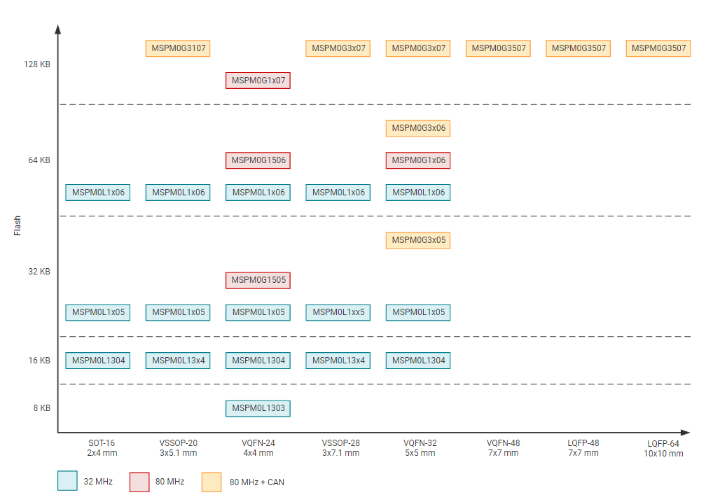
The first step of migration is to choose the correct MSPM0 device for the application.Figure 2-10 shows the portfolio of MSPM0 L and G series family, which can be seen in official website of TI. And Figure 2-11 shows the portfolio of MSPM0 C series. Both portfolios all distinguish the device according to memory and packaging, which makes it easier to have a simple selection.
 Figure 2-10 Portfolio of MSPM0L and MSPM0G
Series
 Figure 2-11 Portfolio of MSPM0C Series
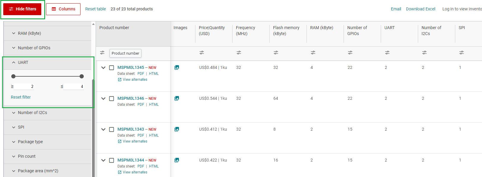
To narrow down to a specific device, the product selection tool plays an import role. In this link, you can use the filter on the left to do Initial screening based on your MCU peripheral requirement. For example, to filter out the MCU that meet the UART number, you can directly use the filter tool to select, and the qualified MCU devices will pop up on the right, as shown in the Figure 2-12, and you can directly go to the device page through the left search text box for detailed information of corresponding device.
 Figure 2-12 MSPM0 Product Selection Tool
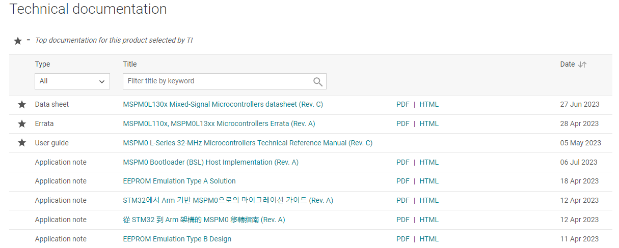
On the device page, the key documents like the data sheet, Technical Reference Manual (TRM) and Errata can be found and downloaded easily, as shown in Figure 2-13. The device-specific data sheet introduces the parameters and functional data information of dedicated MSPM0. The device-specific TRM introduces the application method and characteristics of a series MSPM0. The device-specific errata introduces the ecorrigendum description of MSPM0 related series or versions.
 Figure 2-13 MSPM0 Important Document List
As shown in Figure 2-14, the website also lists the relevant technical documents on MSPM0, the most common being application notes.
 Figure 2-14 MSPM0 Relevant Technical Documentation
List
Figure 2-14 MSPM0 Relevant Technical Documentation
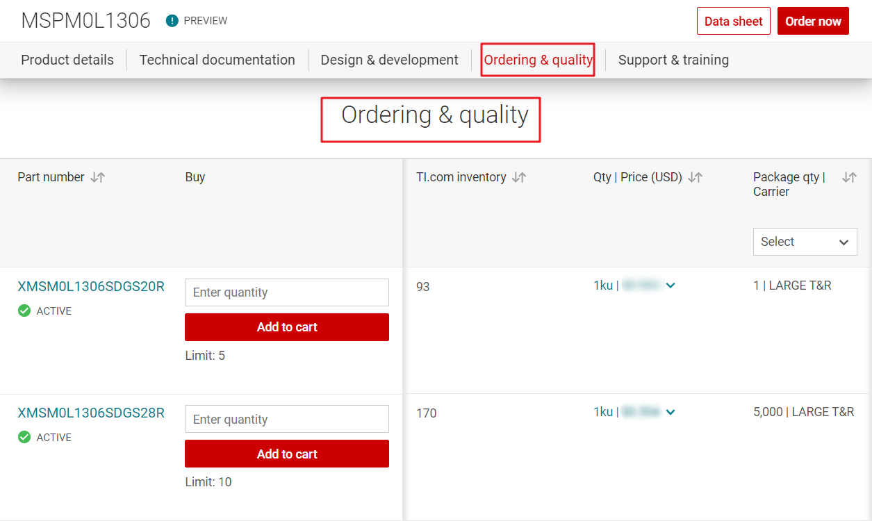
ListAfter completing the selection, you can check the price and other information through ordering and quality, as shown in Figure 2-15.
 Figure 2-15 Ordering and Quality Part View