SLLA380F May 2021 – August 2022 ISO1042 , ISO1042-Q1 , ISO1044 , ISO1050 , ISOW1044
1 Application Brief
Introduction: Isolated CAN
CAN interface has been a very popular serial communication standard in the industry due to its excellent prioritization and arbitration capabilities. In systems with different voltage domains, isolation is typically used to protect the low voltage side from the high voltage side in case of any faults. Isolation also breaks any ground loops allowing only the desired signals to be transmitted, thereby signal quality.
Isolated CAN is used for communication with the microcontroller in a wide range of applications such as solar inverters, circuit breakers, motor drives, PLC communication modules, telecom rectifiers, elevators, HVACs and EV charging infrastructures.
Isolated CAN can be broadly categorized into two types:
- Basic isolation: In some applications like elevators and
HVACs, CAN signaling is used between boards for communication and the CAN lines
are not subjected to high voltage differences as a part of the normal operation.
In such cases, basic isolated CAN would suffice from isolation perspective.
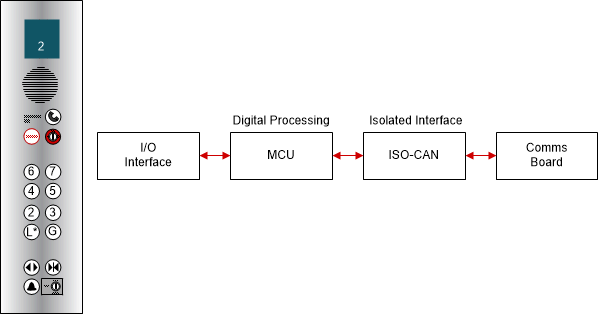
Figure 1-1 shows an example of an elevator where the communication between the calling
button operating panel and the communications board is achieved through isolated
CAN.
 Figure 1-1 Isolated CAN in
Elevators
 - Reinforced isolation: For solar
inverter applications, the working voltage needs are higher and the electrical
safety standard would have to be met by the isolator and hence reinforced
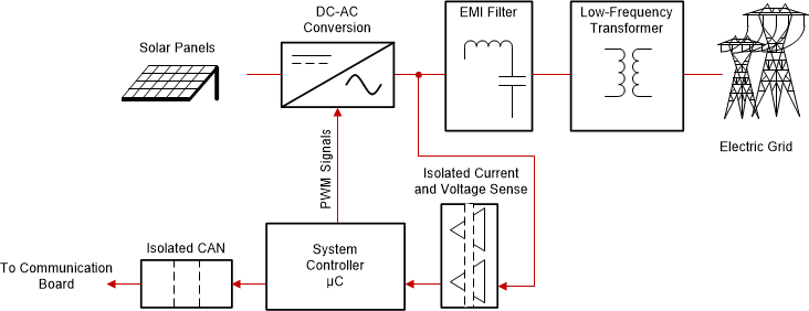
isolation would be required. An example of isolated CAN used between the control
module on the hot side and communication board of a computer or human-machine
interface (HMI) on the cold side is shown in Figure 1-2.
 Figure 1-2 Isolated CAN in Solar
Inverters
In addition to the isolation rating, the other important care-abouts for isolated CAN devices are ESD, EMC, EFT surge performance as the isolated CAN still operates in a noisy industrial environment and could experience some high voltage disturbances.
Performance Considerations
- Stand-off voltage or DC Bus fault protection voltage: This voltage denotes the maximum voltage that can be applied to the CANH and CANL without damaging the device. The probability of the supply short to the CANH/CANL lines depends on the routing of the CANH/CANL signals relative to the high voltage supply lines – if all the signal and supply wiring is in the same harness, then higher stand-off voltage is recommended.
- Data-rate: Classical CAN data-rates are limited to 1Mbps. But newer CAN Flexible Data-rate (FD) transceivers are designed for data-rates up to 5Mbps, thereby enhancing timing margin and to allow for higher data-rates in long and highly-loaded networks. For more information, refer to the CAN FD blog.
- Size: With space constrained applications, discrete implementation of an isolator and CAN transceiver may not be feasible. Integration of isolation and CAN in a single package alleviates this concern.
- Common mode transient immunity (CMTI): CMTI is defined as the maximum rate of change of the common mode voltage on one side of the isolation without affecting the other side. It is measured in dv/dt and higher the CMTI, higher is the protection from common mode swings on one side to the other.
- Common mode voltage range: This voltage determines the variation in the common mode that can be tolerated by the CAN device without causing errors in the data. Higher the common mode range in noisy environments allows for error-free communication. With integrated isolation, the common mode voltage is not as critical as the non-isolated case.
New Isolated CAN
The ISO1042 is latest EMC optimized isolated CAN transceiver with 70-V stand-off and CAN FD. This device combines the high performance of the TCAN1042 core with the robust ISO7721 isolation in a single package to provide galvanically isolated CAN transceiver that meets the specifications of the ISO11898-2 (2016) standard.
Isolation Performance
Table 1-1 shows the comparison of the ISO1042 isolation ratings with the other isolated CAN devices available in the market.
| Parameter | ISO1042 | Competitor A | Competitor B |
|---|---|---|---|
| Working voltage (VRMS) | 1000 | 600 | 800 |
| Isolation voltage (VRMS) | 5000 | 5000 | 5000 |
| Surge test voltage (VPK) | 10000 | 10000 | 6000 |
| Minimum CMTI (kV/μs) | 85 | 25 | 45 |
ISO1042 uses an isolation barrier where the dielectric material, SiO2, is moisture and temperature resistant. This provides the highest working voltage in the industry, ensuring higher margin and longer lifetimes for these devices. With 10 kVPK surge rating, the ISO1042 device meets the reinforced isolation standard. The higher CMTI spec of the ISO1042 provides higher immunity against noise perturbations on either side of the isolator, thereby maintaining signal integrity.
CAN performance
Table 1-2 lists the CAN performance of the various isolated CAN devices.
| Parameter | ISO1042 | Competitor A | Competitor B |
|---|---|---|---|
| CAN FD support | Yes | No | Yes |
| Maximum Data-rate (Mbps) | 5 | 1 | 5 |
| Bus Protection Voltage (V) | ±70 | ±36 | ±58 |
| Common Mode Voltage Range (V) | ±30 | Not specified | ±25 |
| VCC1 Range (V) | 1.71 to 5.5 | 3 to 5 | 3 to 5.25 |
| VCC2 Range (V) | 4.5 to 5.5 | 4.75 to 5.25 | 4.8 to 5.3 |
The ISO1042 supports CAN FD up to 5Mbps with the classical CAN data-rates of 1Mbps, thereby providing increased data payload by almost 8 × when compared to classical CAN. The highest bus protection voltage provides large margin for this device as compared to other devices to withstand mis-wiring of the cables or shorts to the power supply. In addition, the high common mode range allows the device to be operative in a noisy system. The ISO1042 logic levels of 1.71 V to 5.5 V allows connections to the MCU directly without any level shifters. Finally the secondary side supply has 10% tolerance easing the requirements on the LDO used for isolated power supply.
Size considerations: Package
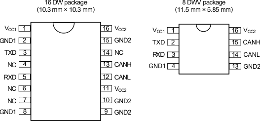
The ISO1042 is available in 2 packages as shown in Figure 1-3. The 16 pin SOIC (DW) is the industry standard isolated CAN package while the 8 pin SOIC (DWV) is a much smaller package that reduces the board space by half when compared to the other solutions available today. Both these packages provide 8-mm creepage and clearance, making them suitable for basic and reinforced applications.
 Figure 1-3 ISO1042 Package
Options
Figure 1-3 ISO1042 Package
OptionsConclusion
The ISO1042 device is a new isolated CAN device that has superior isolation and CAN performance to meet the needs of the industrial and automotive applications. Robust isolation coupled with high stand-off voltage and increased speeds enables efficient communication in noisy environments.
Small package allows further reduction of board space in addition to reduced components due to integration of isolation and CAN with protection features. For a discrete and integrated isolated CAN solution, read How to Isolate Signal and Power in Isolated CAN Systems.
| Device | Optimized Parameters | Performance Trade-Off |
|---|---|---|
| ISO1044 | Ultra-small isolated CAN transceiver | 3-kVRMS isolation and ±58-V bus fault protection |
| ISOW1044 | 5-kVRMS, isolated CAN FD transceiver with integrated DC/DC converter | Integrated low radiated emissions DC/DC converter reduces board space and simplifies designs |