SLLA486B May 2020 – October 2024 ISO1042 , ISO1042-Q1 , ISO1044 , ISO1050 , ISOW1044
- 1
- Top Design Questions About Isolated CAN Bus Design
- Trademarks
- 1 When Do I Need to Isolate CAN?
- 2 What are the Options Available to Isolate CAN Bus?
- 3 Now That I Have Isolated CAN Signal Path, How Do I Generate Isolated Power?
- 4 What’s the Reason Behind Terminating the Bus, Do I Need it, and How to Achieve it?
- 5 What’s the Difference Between Common Mode Range and Bus Standoff Mentioned in Data Sheet?
- 6 Now That I Have Taken Care of the Termination Resistor, What Other Components do I Need on the Bus Side?
- 7 When Connecting Isolated CAN Nodes in a Network, What Should be Done with the Floating Bus-Side Ground Connection?
- 8 Is There a Limitation on Minimum Data Rate That I Can Operate? What About the Maximum Data Rate Achievable in a Network?
- 9 Is There a Limit on Maximum Number of Nodes That I Can Connect in CAN Network?
- 10What Factors Decide the Maximum Communication Distance in a CAN Network?
- 11What is the Maximum Value of Bus Capacitance That Can be Introduced Between CANH to GND and CANL to GND? Can Higher Capacitance Damage the Device?
- 12Is There a Way to Extend the Maximum Communication Distance?
- 13What is Stub Length? What are the Design Considerations Around it?
- 14I am Seeing Larger Differential CAN Voltage for Some Bits of CAN Packet Compared to Rest of the Packet When I am Communicating in a Network with Multiple Nodes Connected. Why?
- 15References
- 16Revision History
11 What is the Maximum Value of Bus Capacitance That Can be Introduced Between CANH to GND and CANL to GND? Can Higher Capacitance Damage the Device?
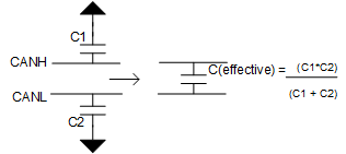
CANH to GND or CANL to GND capacitance will eventually end up as differential capacitance across CAN bus.
 Figure 11-1 CAN Bus Capacitance
Isolated CAN data sheet gives rise/fall times with 100 pF bus capacitance, but if differential capacitance is increased, driver rise and fall times will slow down eating up the timing budget. Various components will contribute to this capacitance:
- External protection components such as CMC, TVS etc
- Cable (typical CAT5 cable can offer 50 pF/meter mutual capacitance)
- Connector
- Number of nodes on bus (each node will offer certain differential capacitance) across the bus
Recessive to dominant edge will depend on the driver to charge up this differential bus capacitance. Usually this process will be faster given an active current source is charging up this capacitance. On dominant to recessive edge, driver is turned off, so this transition will happen due to RC decay of the network. Here R is the effective differential resistance, say 60 ohm (two terminations in parallel). C is the effective differential capacitance of the network (which is the sum of all 4 components that were stated above as all are in parallel).
Say L is total cable length in meter, N is number of nodes each offering CID differential capacitance per selected ISOCAN data sheet (ignoring external CMC / TVS, and connector capacitance just for simplicity here):
- RC time constant will decay the dominant to recessive edge. This should complete going below 500 mV (recessive lower going threshold of CAN receiver: VIT) just before 75% of bit width (assuming CAN controller is sampling around this time)
- Assuming T is minimum bit period (corresponding to max data rate of the application)
Entering values in Equation 2.
From previous equation, maximum bus capacitance that can be introduced across the bus, Cmax can be calculated. CANH to GND and CANL to GND can be double this value. This is the theoretical maximum. Components ignored will also impact. Our recommendation to the customer is to thoroughly test for any bit errors in their system.