SLOU558B August 2022 – January 2023 DRV8452 , DRV8462 , DRV8962
- Abstract
- Trademarks
- 1 Introduction
- 2 Jumpers Table and Setup
- 3 Software Setup
- 4 Hardware Setup
- 5 Launching the DRV84xx_DRV82x2_DRV89x2-EVM GUI Application
- 6 GUI Operations DRV8461EVM, DRV8462EVM, and DRV8462VEVM
- 7 GUI Operations DRV8962EVM and DRV8962VEVM
- 8 GUI Operations DRV8262EVM and DRV8262VEVM
- 9 Updating Firmware
- 10Evaluation Hardware Overview
- A Appendix A
8.2 DRV8262 Parallel Single H-Bridge
There are two ways to connect the outputs to parallel the H-bridge.
Wire method:
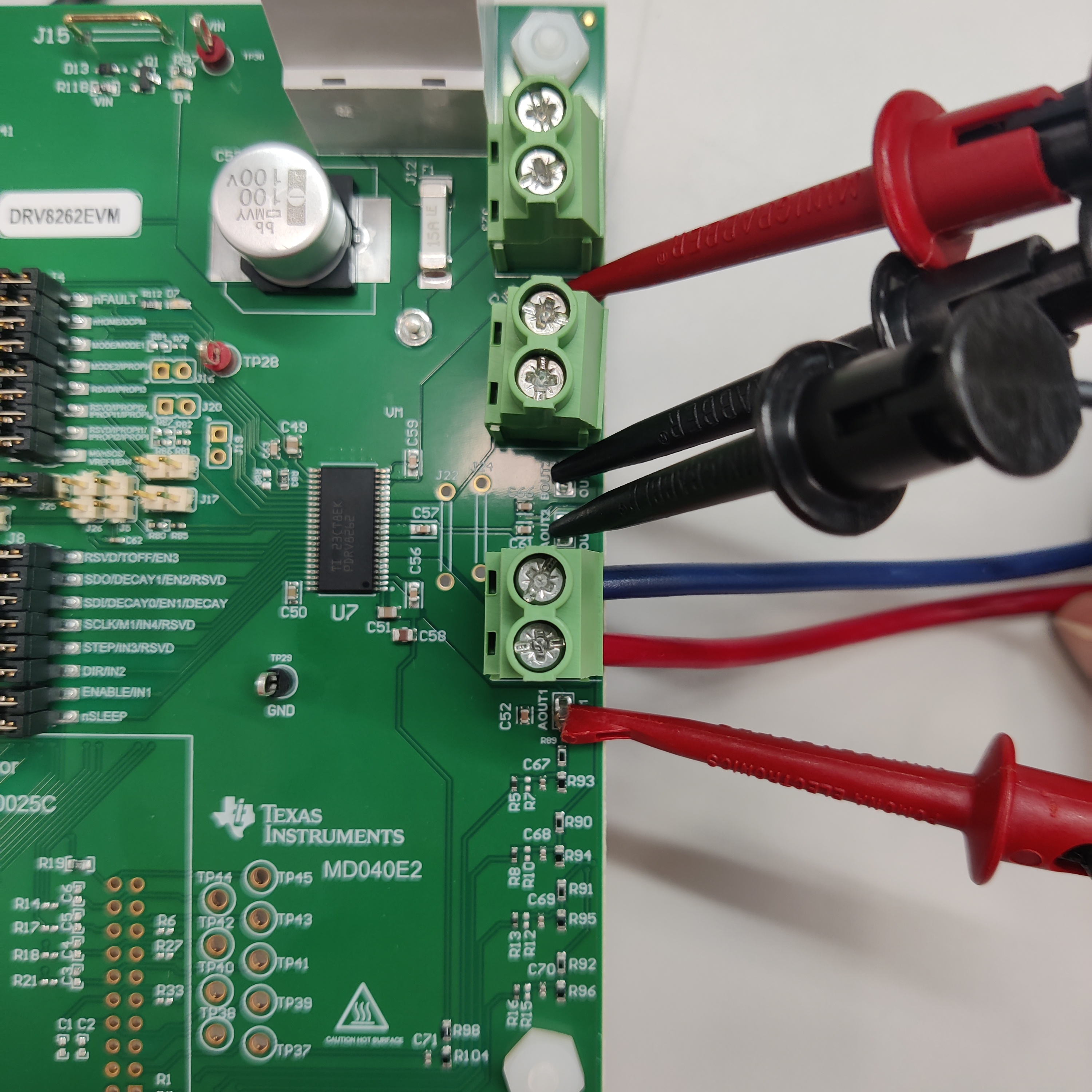
Using an appropriately sized wire based on the desired current, short terminals OUT1 and OUT3.
Using an appropriately sized wire based on the desired current, short terminals OUT2 and OUT4.
Connect motor to screw terminal J13 or to screw terminal J14
Note: The MD040E2 revision EVM PCB silk screen has the following errata. Higher versions (MD040A) have this fixed.- The Silk screen says OUT3, it should say OUT4
- The Silk screen says OUT4, it should say OUT3
 Figure 8-7 Parallel Single H Bridge Connection.
 The red leads are connected to each other and the black leads are connected to each other.
Bar Method (Recommended):
Populate J22 and J24 with D3082-05 or equivalent component.
Connect motor to screw terminal J13 or to screw terminal J14
Go to the “LOAD CONTROL” tab in the “Driver Control” page. The VM Voltage widget will read out the input voltage to J12. Change MODE1 to "Single H Bridge". Using the MODE2 drop down menu choose "Phase/Enable (PH/EN)" mode. Set the “Motor Driver” to “Awake”.
Note - the above screenshot has not been updated - the most recent version of the GUI is DRV84xx_DRV82x2_DRV89x2-EVM-GUI with Firmware Version 0.24. Figure 8-8 Load Control Page Phase/Enable Mode
Phase/Enable Mode Evaluation: Press the “Start Drive 1 ” button. Leave the “Direction” setting as required by the application. Rest of the settings during these tests should be left with default positions and values. Set IN1 Duty Cycle to the desired value. The motor will start spinning in one direction and the motor current will be displayed in the BRIDGE-1 CURRENT display window. Change the “Direction” setting. The motor speed will ramp down to a standstill and then change direction and ramp up speed corresponding to the set duty cycle. The motor current will be displayed in the BRIDGE-1 CURRENT display window. Press the “Stop Drive 1” button. The motor will ramp down and stop.
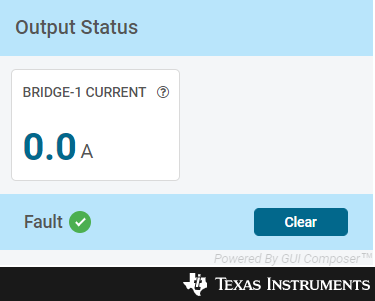
 Figure 8-9 Output Status
PWM Mode Evaluation: Using the MODE2 drop down menu choose “Pulse Width Modulation (PWM)” mode.
Note - the above screenshot has not been updated - the most recent version of the GUI is DRV84xx_DRV82x2_DRV89x2-EVM-GUI with Firmware Version 0.24. Figure 8-10 Load Configuration PWM Mode
In order to account for the MODE2/IPROPI4 pin input level requirements the MODE2/IPROPI4 jumper short must be removed for proper operation of the bridge in this mode prior to setting the "Motor Driver" to "Awake".
 Figure 8-11 MODE2/IPROPI4 Needs to be removed to operate in PWM mode.
The LOAD CONTROL window will change to PWM control mode with two PWM settings sliders as shown in #GUID-E9EDA09F-471E-4D8E-9045-A9A795A7B027
Press the “Start Drive 1” button. The two duty cycle settings sliders will become active now. Set IN1 Duty Cycle slider to the desired value. The Motor will spin in one direction and its current will be displayed in the BRIDGE-1 CURRENT display window. IN2 Duty Cycle slider will be grayed out during this time. Set IN1 Duty Cycle slider to 0%. Motor will ramp down to a stop. Both IN1 and IN2 Duty Cycle sliders will be active again.
Set IN2 Duty Cycle slider to the desired value. Motor will spin in the opposite direction now and its current will be displayed in the BRIDGE-1 CURRENT display window. IN1 Duty Cycle slider will be grayed out during this time. Press the “Stop Drive 1” button. Motor will ramp down to a stop. Switch the “Motor Driver” widget to “Asleep”. Insert the MODE2/IPROPI4 jumper short back in its position after PWM mode bridge control evaluation is completed.