SLOU558B August 2022 – January 2023 DRV8452 , DRV8462 , DRV8962
- Abstract
- Trademarks
- 1 Introduction
- 2 Jumpers Table and Setup
- 3 Software Setup
- 4 Hardware Setup
- 5 Launching the DRV84xx_DRV82x2_DRV89x2-EVM GUI Application
- 6 GUI Operations DRV8461EVM, DRV8462EVM, and DRV8462VEVM
- 7 GUI Operations DRV8962EVM and DRV8962VEVM
- 8 GUI Operations DRV8262EVM and DRV8262VEVM
- 9 Updating Firmware
- 10Evaluation Hardware Overview
- A Appendix A
6 GUI Operations DRV8461EVM, DRV8462EVM, and DRV8462VEVM
- Go to the “STEPPER MOTOR CONTROL” tab in the “Driver Control” page. Set the “Motor Driver” to “Awake” and “Driver Outputs” to “Enabled”. With default settings click on the “Start Input-based STEP” button. The motor spins in one direction. Change the direction using the “Input-based Direction” control. The motor spins in the opposite direction.
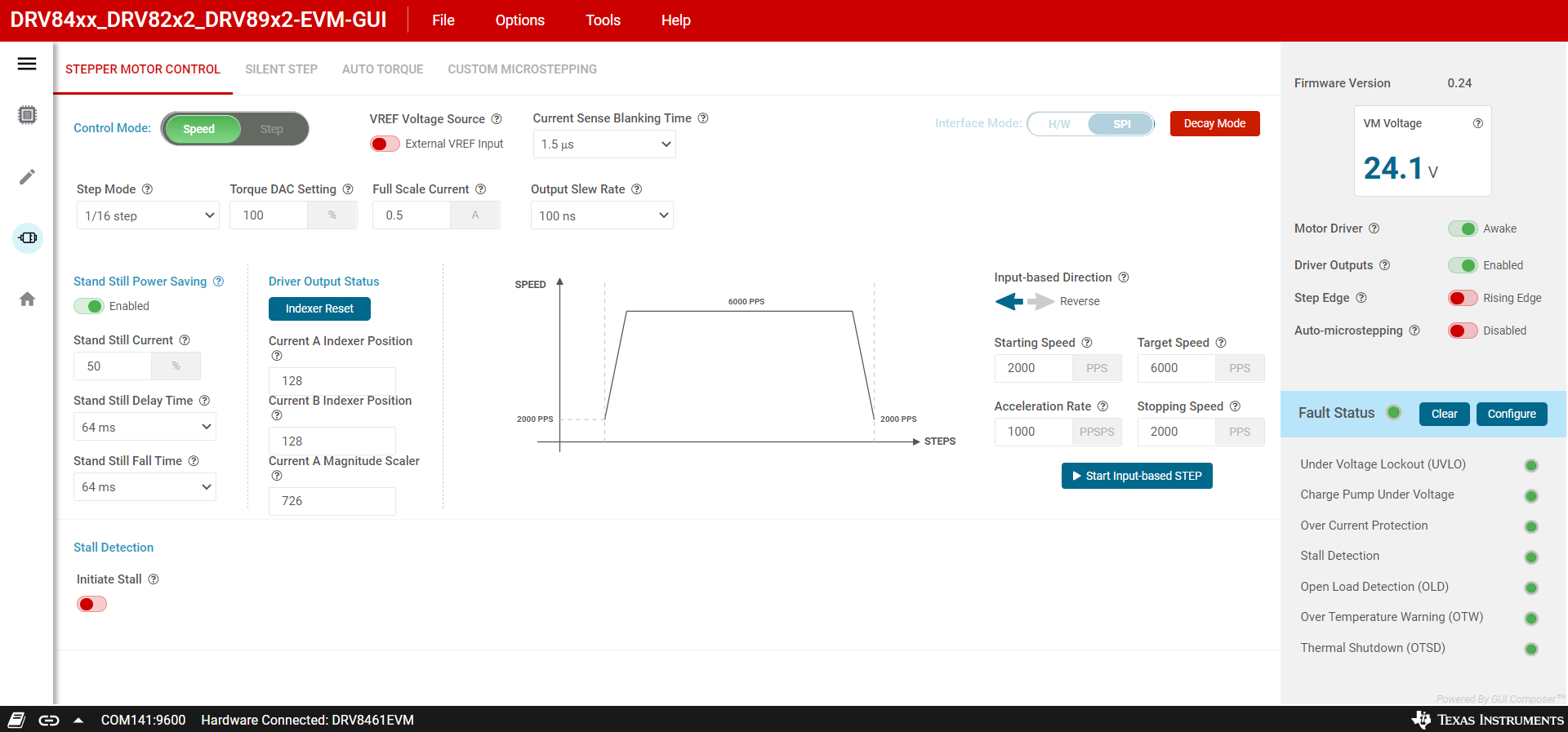 Figure 6-1 Stepper Motor Control
 - The “Register Map” menu displays all the device Registers. Register values can be modified directly either using the “Field View” panel or by changing the hexadecimal data displayed in the “Value” column.
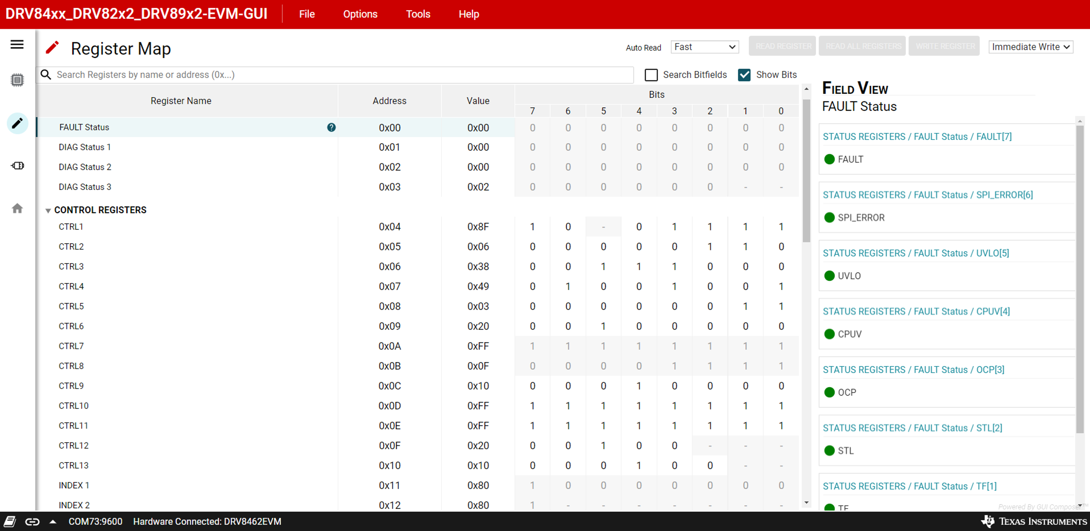 Figure 6-2 Register Map
- All Registers settings can be saved as a ‘regs.json’ file using the “File” menu “Save Registers” option. The saved values can be loaded back to the Registers from the saved ‘regs.json’ file using the “File” menu “Load Registers” option.
The CTRL14 register reports the VM_ADC value converted into an equivalent voltage range, which is only displayed on the register map page. The VM voltage reported on the main GUI panel is measured by the microcontroller with higher precision, and is not a representation of the motor driver register.
- The device features can be evaluated using the tabs highlighted in #GUID-E73207FA-B34F-4812-9AD2-5344579EA97A
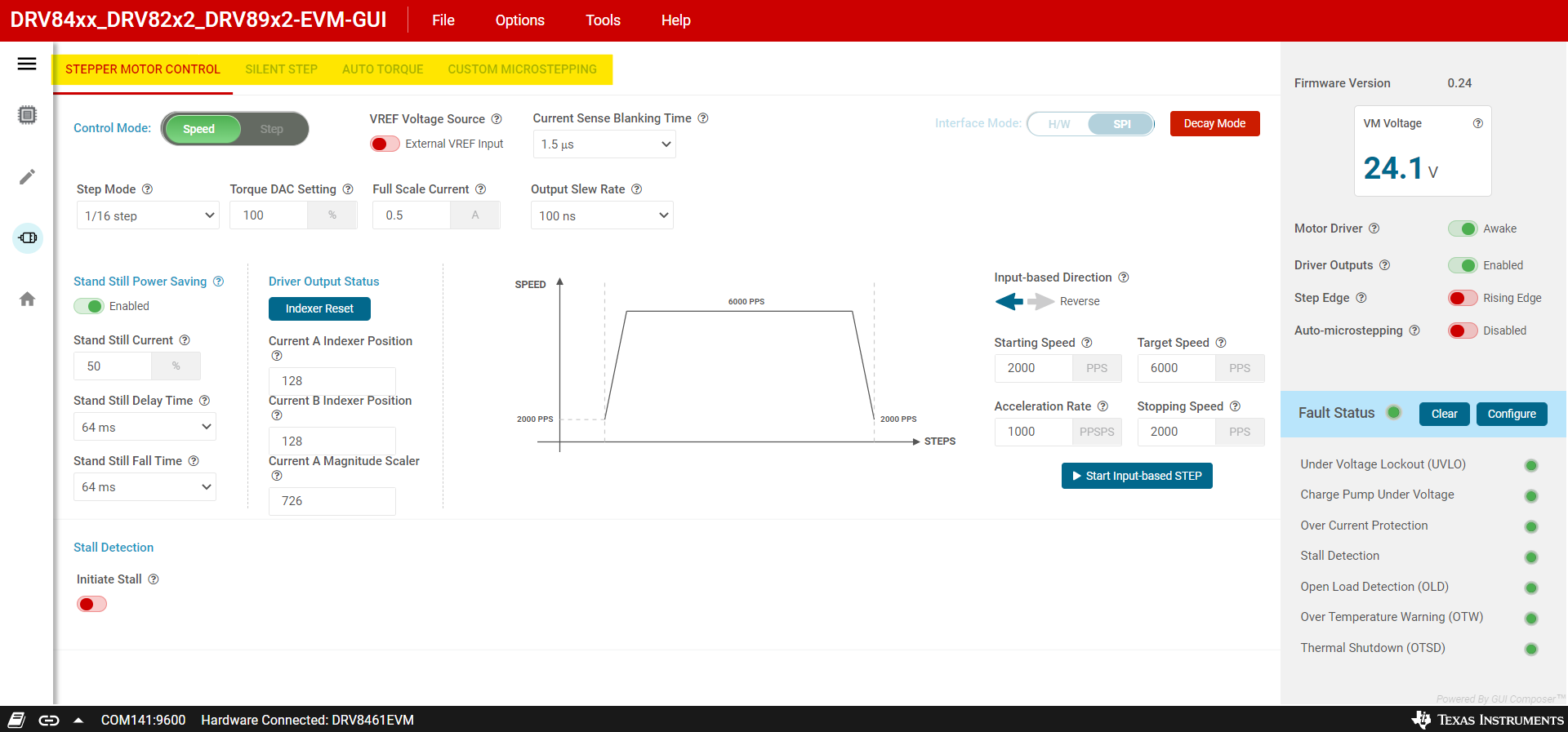 Figure 6-3 Driver Control Menu
 - Refer to the DRV8462 datasheet or DRV8461 datasheet to understand the integrated features of the stepper motor driver device. Only the key features are described below. The GUI provides access to all the features in the device.
- Stand Still Power Saving: This feature defines the hold current level while the motor is in stand still. Typically hold current required can be significantly lower than run current. This feature can save power as well as avoid unnecessary heating of the motor. The default setting for the “Stand Still Current” is 50 % of the run current defined by “Torque DAC Setting” and “Full Scale Current”. The minimum value that can be input is 1 %. Enable this feature and set the desired hold current value as well as required delay times designed for your application.
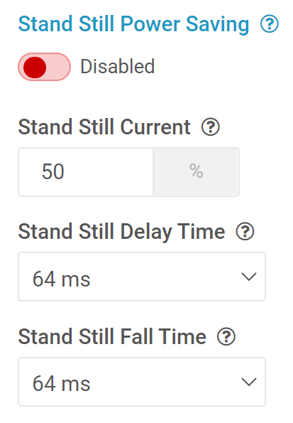 Figure 6-4 Stand Still Power Saving
 Driver Output Status: This section displays the indexer position forcurrents A and B in the indexer table of the driver device. This value goes from 0 to a maximum of 255, then decreases back to a minimum of -255 via 0 and then increases back to 0. This sequence is repeated as long as the STEP input is active. Clicking the "Indexer Reset" button resets the indexer position to its default value in the table for both Current A and Current B. Clicking "Indexer Reset" has the same effect as going to the Register Map page and setting the IDX_RST bit in CTRL1, which clears itself immediately after the indexer is reset. The indexer reset action does not reset any other register setting. In addition to these, the magnitude scaler of Current A at its corresponding indexer position is also displayed. This is a 10-bit value 0 to 1023 contained in registers INDEX5 (upper eight bits) and INDEX4 (lower two bits). When the scaler value is 1023 it represents the maximum current value of Current A. The scaler value is not affected by the torque DAC setting, stand still current setting or the auto-torque current DAC setting.
- Stand Still Power Saving: This feature defines the hold current level while the motor is in stand still. Typically hold current required can be significantly lower than run current. This feature can save power as well as avoid unnecessary heating of the motor. The default setting for the “Stand Still Current” is 50 % of the run current defined by “Torque DAC Setting” and “Full Scale Current”. The minimum value that can be input is 1 %. Enable this feature and set the desired hold current value as well as required delay times designed for your application.
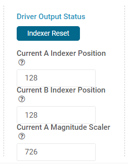 Figure 6-5 Driver Output Status.
 - Auto-microstepping: When enabled this feature automatically interpolates the step input pulses to the selected auto microstepping modes in the drop down menu of RES_AUTO.
 Figure 6-6 Auto Microstepping & RES_AUTO
 - Step Edge: This setting selects step input response to either rising edge or both edges. The default setting is rising edge. When “Both Edges” option is selected, the motor can step with double the target speed. Set the “Target Speed” accordingly to avoid a motor stall.
 Figure 6-7 Step Edge
 - Control Mode: This is a GUI app feature which allows selection between “Speed” mode and “Step” mode. In speed mode the motor can run at the set target speed using the defined acceleration and deceleration rate motion profile. In “Step” mode the motor can be stepped to the desired position by setting the required number of steps at the set target speed. When target speed is set to 1 PPS (pulse per second) setSetting the starting, stopping, acceleration rate and target speed to the same value will start motor directly at the target speed. To transition from a target speed above 400 PPS to a speed below 400 PPS or vice versa you must stop the motor then start the motor again. This only applies to the GUI use with our EVM, it is not a motor driver limitation.
 Figure 6-8 Control Mode
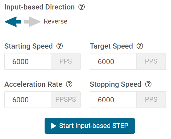 Figure 6-9 Input Based STEP Control Panel
 - Stall Detection: This feature can be enabled by using the “Initiate Stall” slide switch. While enabled, all stall detection settings and features are revealed by the GUI. Stall detection can be used in either learn mode which automatically learns the stall threshold value using a learn procedure or manual stall threshold value entry mode by disabling the “Learn Mode”.Stall detection requires the drive to operate in Smart Tune Ripple Control Decay mode which is the default setting of the device. The Decay mode can be modified using the “Decay Mode” GUI push button in the STEPPER MOTOR CONTROL tab. Test point A3 on the EVM outputs an analog voltage equivalent to the Torque Count updated once every 8 ms. Torque Count = (Output Voltage x 4095) / 3.3.
 Figure 6-10 Stall DetectionThe GUI app has a feature to disable stall detection during acceleration. The default setting for this is “Disabled”. Wait for the acceleration to complete which is indicated by the LED D10 off, before performing a stall threshold learn.
 Figure 6-11 Decay ModeNote: The torque count is 4095 when the stall detection is disabled during acceleration. After the acceleration is completed, stall detection is automatically enabled and the actual torque count is displayed.In the learn mode, run the stepper motor at the desired target speed with no load. Wait for the “Stall Detection” message “Please stall motor to complete Stall Threshold learning sequence” and “Relearn Stall Threshold” push button to appear. Then manually stall the motor by safely using a pair of pliers with soft jaws or if you are using a linear system with mechanical travel end hard stop positions, allow the motor to hit the physical stop.A successful stall threshold learning will be indicated by a check mark icon and text “Stall threshold learning sequence complete”. A relearn can be done at any time by pressing the “Relearn Stall Threshold” button. If the “Active Stall Detection” is set to “Stop driving after stall” and “Reverse direction on stall fault” to off, which happen to be the default setting, the motor will stop immediately after a learning is completed and the “Stall Detection” indicator in the GUI status panel will turn red. The motor can be run again after pressing the “Clear” button to the right of the Fault Status indicator in the GUI. If you want to keep driving after stall you can enable it below.
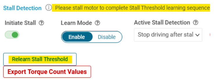 Figure 6-12 Stall Threshold LearningIn manual stall threshold entry mode run the motor with “Stall Threshold” slider set to zero. The torque count it displayed as well as plotted in the graph vs. time. Use the x8 multiplier if the torque count is low while using high DCR stepper motors. Record the torque count and set the threshold to 50 % of the torque count value or lower. Follow the same procedure as in the learn mode operation to detect a motor stall. Pressing the “Export Torque Count Values” exports 512 values of the historical torque count to an Excel file.
 Figure 6-13 Keep Driving After Stall OptionNote: In this pre-production silicon version there is a known issue that can not clear the STL bit in the FAULT register. As a work around, use either the “Keep driving after stall” setting for “Active Stall Detection” or switch on “Reverse direction on stall fault” after a successful learning sequence.
 Figure 6-14 Torque Count and Export Torque
 - Custom microstepping: To setup and enable this feature, use the CUSTOM MICROSTEPPING tab. Custom microstepping allows the user to define a custom current waveform other than the sine wave defined by the integrated microstepping indexer. When custom microstepping is enabled the integrated microstepping settings are ignored by the driver regardless of its setting.
A drop down menu allows the user to choose between “User defined” (default) or three other preset options available in the GUI. This is a GUI feature provided for ease of use. Click on the desired option, for example “Triangular” to automatically populate the Registers CUSTOM_CURRENT1 to CUSTOM_CURRENT8. Registers CUSTOM_CURRENT1 to CUSTOM_CURRENT8 define the first quadrant of the electrical cycle of the phase currents. Rest of the quadrants are automatically populated by the device including the zero values of the full electrical cycle. If the “User defined” option is selected, enter the values for a desired waveform. Enable the “Custom-microstepping” slide switch after the Registers are populated with the required values.
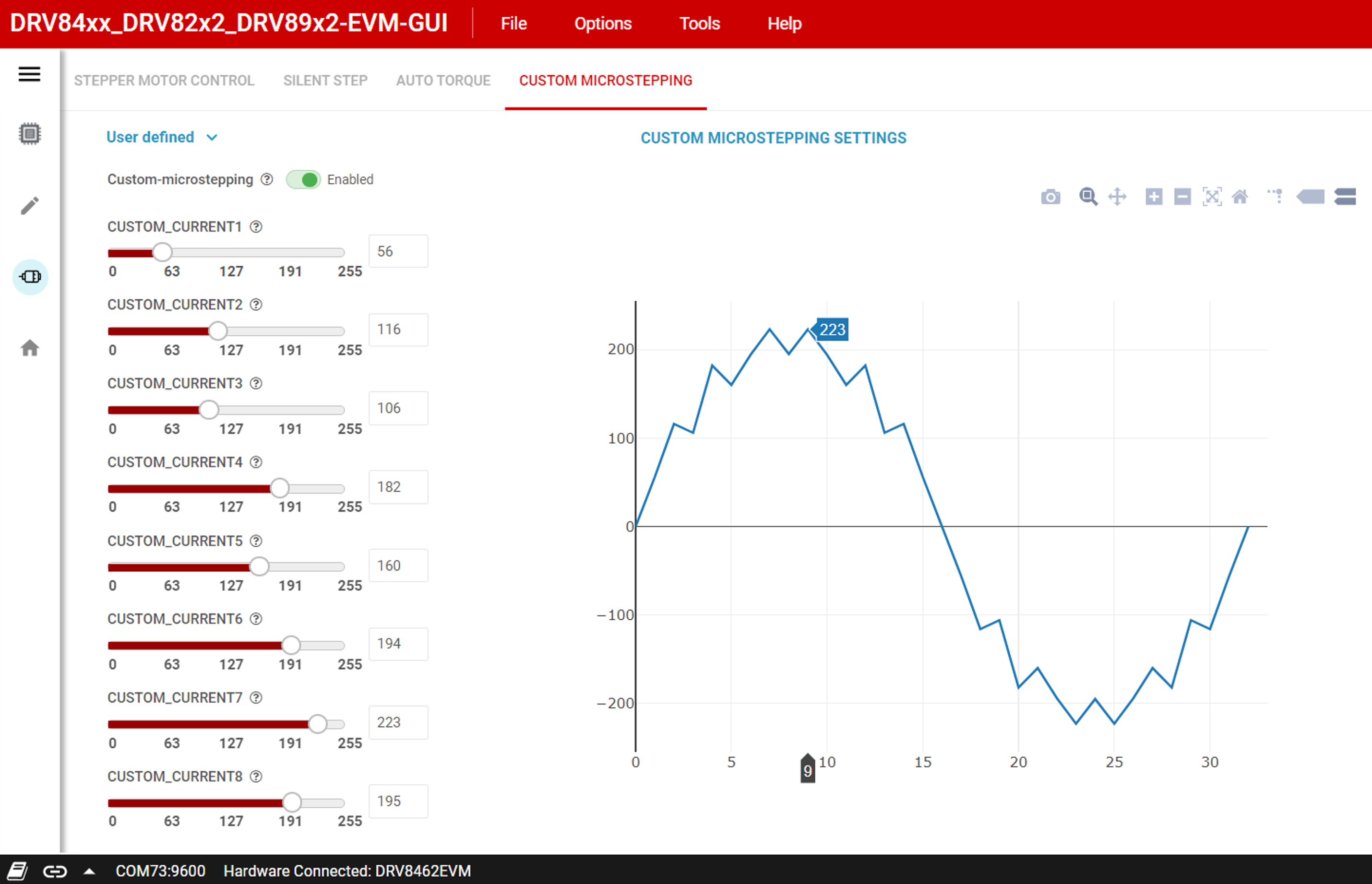 Figure 6-15 Custom Microstepping
 - Silent step Decay mode: To setup and enable this feature use the SILENT STEP tab.Note: Stall Detection works only in Smart Tune Ripple Control Decay mode. Disable stall detection while Silent Step Decay Mode is used.
Set the “Silent Step Decay Mode” slide switch to “Enabled”. Select the desired silent step transition threshold step rate for your application. Start with a KP value of 32 and fine tune KP and KI to fit your application. Silent step decay mode benefits low stepping rate operation of the motor especially with low microstepping settings such as 1/4, 1/2, and Full step.
Use the following procedure to demonstrate this feature. Start with the default settings of the GUI in “Speed” Control Mode. Reduce the “Target Speed” to 2000 PPS and change “Step Mode” to 1/4 Step. Run the stepper motor. While running with these settings the motor usually generates an audible noise. Switch to the SILENT STEP tab. Set the “Silent Step Decay Mode” slide switch to “Enabled”. Select the “Silent Step Transition Threshold” to 400 Hz. Set a KP value of 32. The motor runs quietly.
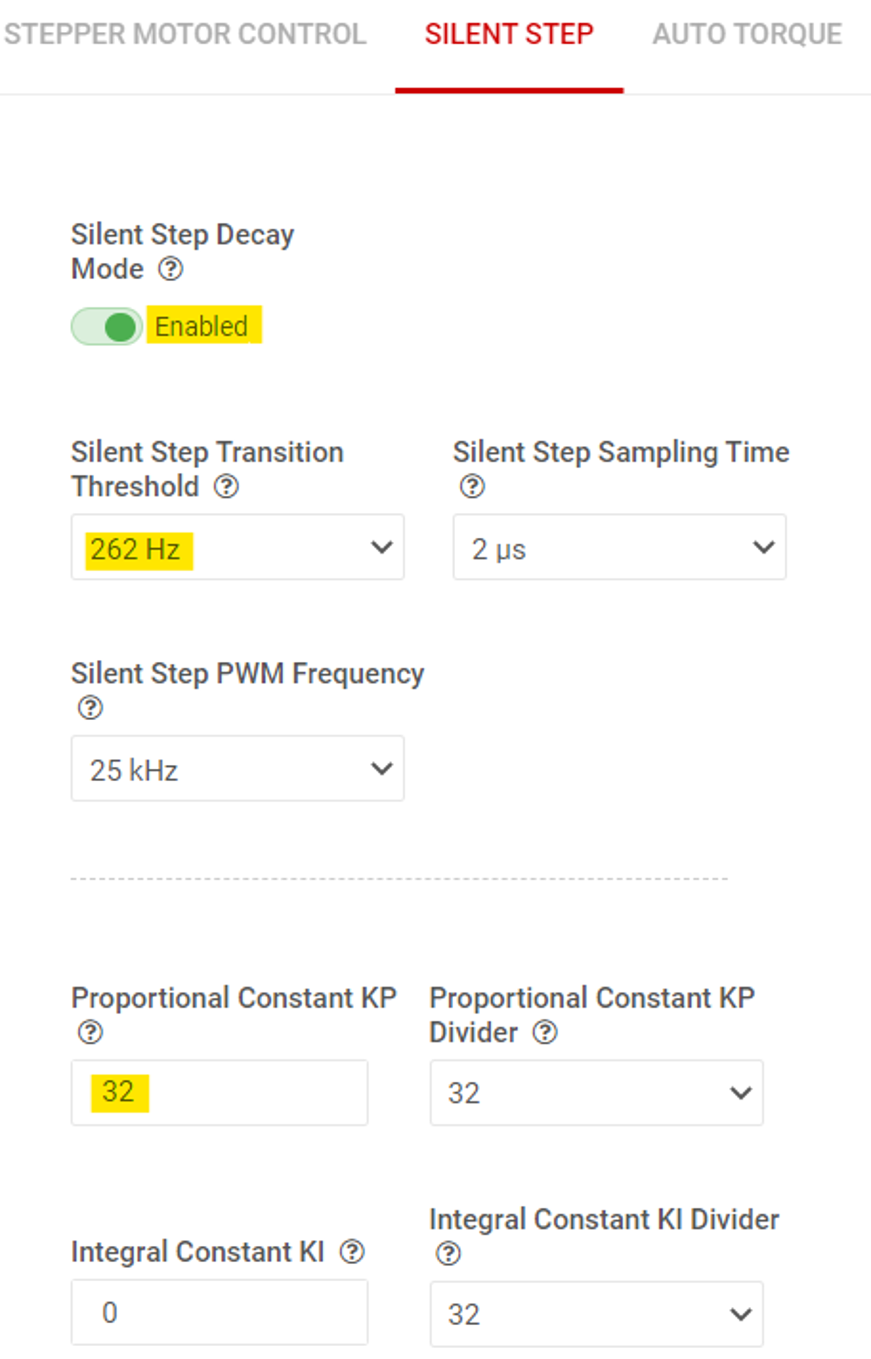 Figure 6-16 Silent Step Control Panel
 - Auto Torque: To setup and enable this feature, use the AUTO TORQUE tab. The following example describes setting up Auto Torque with a J-4218HB2401 NEMA17 bipolar Stepper motor rated 1.7 A, commonly used in 3D printers. A 24 V power supply with > 3 A current rating is used for powering the EVM.
- Start with the default settings of the EVM. Performing an EVM firmware reset using push button S1 will the default settings of the EVM are loaded. Click on the DRV8462EVM icon from the GUI home page to establish connection between the GUI app and the EVM.
- Go to the “Motor Control” menu in the left-hand side menu bar. Set “Motor Driver” to “Awake”. Increase the Full-Scale Current setting to 2 A in the STEPPER MOTOR CONTROL tab. Set “Driver Outputs” to “Enable”. Start the motor using the “Start Input based STEP” push button.
- Switch to the AUTO TORQUE tab of the GUI. Enable Auto Torque mode using the slide switch.
- Next, while the motor is running unloaded and with the default settings of the “Learn” parameters, initiate a learn by pressing the “Auto Torque Learn” push button. A green check mark with text “Learn Completed” can appear as soon as the learning is completed. Relearning can be done at any time with the motor running unloaded at any time by pressing the “Auto Torque Learn” push button. Preproduction silicon required the KP value to be set to 1 before learn could be initiated. Production silicon does not have this requirement.
- Configure the minimum and maximum current limit values in “Loop Regulation” section. These are 8-bit integer values, 0 to 255 in decimal. Set the minimum current limit value to 48 which can be equal to (48/256) * 2 A or 375 mA. With 375 mA drive current, this stepper motor will have sufficient torque to run with a light load without losing steps or stalling. This is the criteria for choosing the minimum current limit value in an application. Set the maximum current limit value to 192 which can be equal to (192/256) * 2 A or 1.5 A. A higher maximum value can be chosen if needed by the application. Auto torque can allow over driving the motor for short periods of time during transient higher load torque.
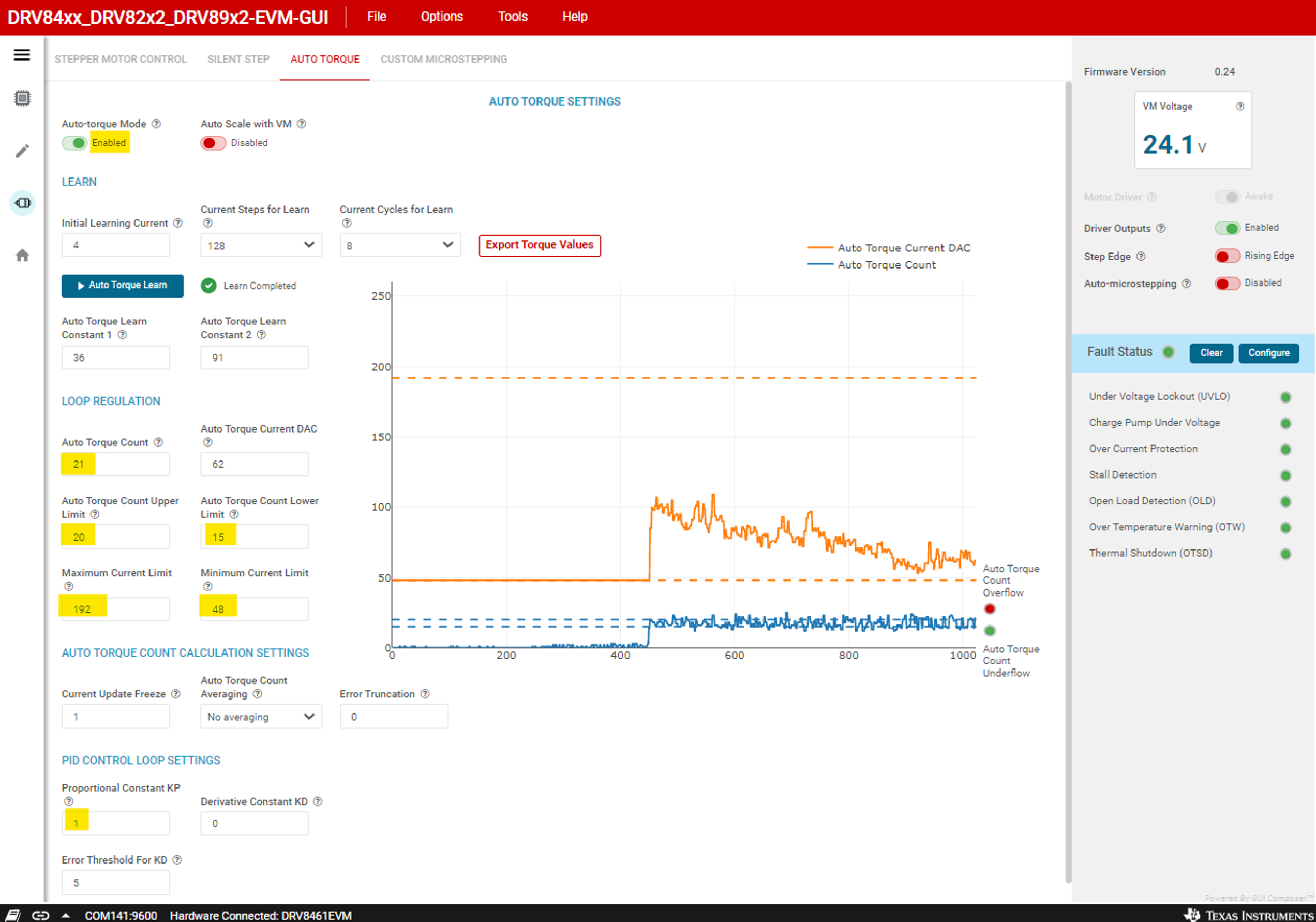 Figure 6-17 Auto Torque Control Panel
The chart on the right displays data for the following items:
Auto Torque Count (solid blue line)
Auto Torque Current DAC (solid orange line)
Auto Torque Count Upper Limit (upper dashed blue line)
Auto Torque Count Lower Limit (lower dashed blue line)
Maximum Current Limit (upper dashed orange line)
Minimum Current Limit (lower dashed orange line)
Auto Torque Count Overflow (upper right red/green error indicator)
Auto Torque Count Underflow (lower right red/green error indicator)
Pressing the “Export Torque Count Values” exports 1024 values of the historical torque count to an Excel file.
- Now, observe the “Auto Torque Count” values with no load. Use the range of values observed to set the Auto Torque Count upper and lower limits. The auto-torque algorithm maintains the ATQ_CNT value within the hysteretic band defined by ATQ_UL and ATQ_LL, by modulating the full-scale current between 375 mA and 1.5 A.
- Please refer to the DRV8462 data sheet for detailed description of the Auto Torque feature including details on how to setup and tune its operation to fit your application.
- In addition to the SPI-based Register controlled operation, the DRV8462 device also supports GPIO controlled operation described in the device data sheet. The GUI also allows operating the device in this mode. The GUI comes up with “SPI” controlled operation by default. To operate the device with GPIO control select “H/W” in the “Interface Mode” selector in the STEPPER MOTOR CONTROL tab. The selector can be changed only while the “Motor Driver” slide switch is in “Asleep” position.
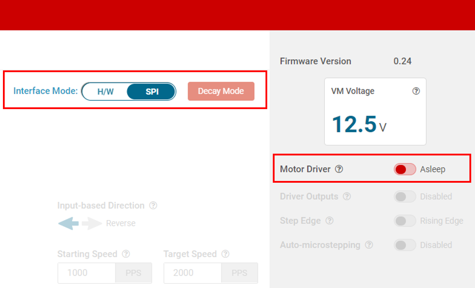 Figure 6-18 Interface Mode Selector
 - Fault Configuration: While in SPI mode a Fault Configuration Console, is available for setting the necessary fault detection and reporting schemes. Press the “Configure” push button widget in the Fault Status panel as shown in Fault Configuration Push Button Widget. The “Fault Configuration” window can pop up immediately.
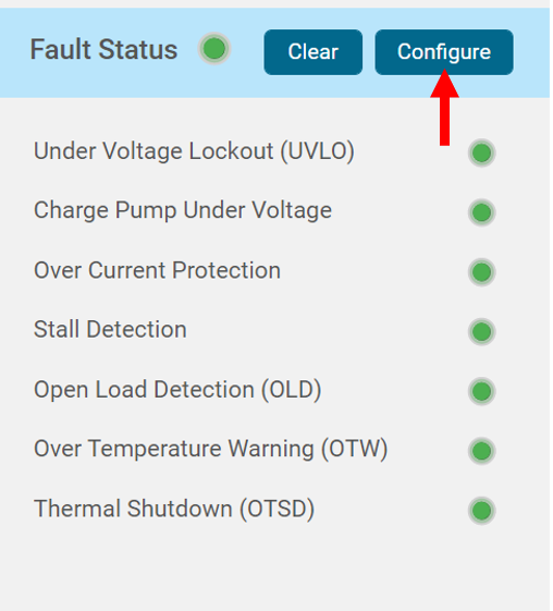 Figure 6-19 Fault Configuration Push Button Widget
- This console allows the user to Enable/Disable Open Load Detection, Open Load Detection time etc., Refer to Fault Configuration Popup Window to review and modify fault reporting and configuration as needed. After all the modifications are made the popup window can be closed to access the main GUI interface for further evaluation.
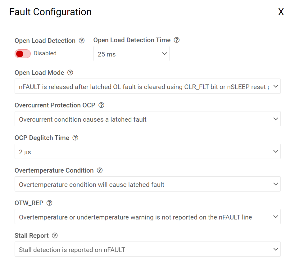 Figure 6-20 Fault Configuration Popup Window
- This console allows the user to Enable/Disable Open Load Detection, Open Load Detection time etc., Refer to Fault Configuration Popup Window to review and modify fault reporting and configuration as needed. After all the modifications are made the popup window can be closed to access the main GUI interface for further evaluation.