SLUUC37C july 2019 – august 2023 BQ75614-Q1 , BQ79616 , BQ79616-Q1 , BQ79656-Q1
- 1
- BQ79616-Q1 and BQ75614-Q1 Evaluation Modules
- Trademarks
- General Texas Instruments High Voltage Evaluation (TI HV EVM) User Safety Guidelines
- 1 General Description
- 2 Theory of Operation - Stackable BQ79616EVM
- 3 Theory of Operation - Standalone BQ75614EVM
- 4 Connectors
- 5 Quick Start Guide
- 6 Physical Dimensions
- 7 BQ79616EVM Schematic, Assembly, Layout, and BOM
- 8 BQ75614EVM Schematic, Assembly, Layout, and BOM
- 9 BQ79656EVM Schematic, Assembly, Layout, and BOM
- 10Revision History
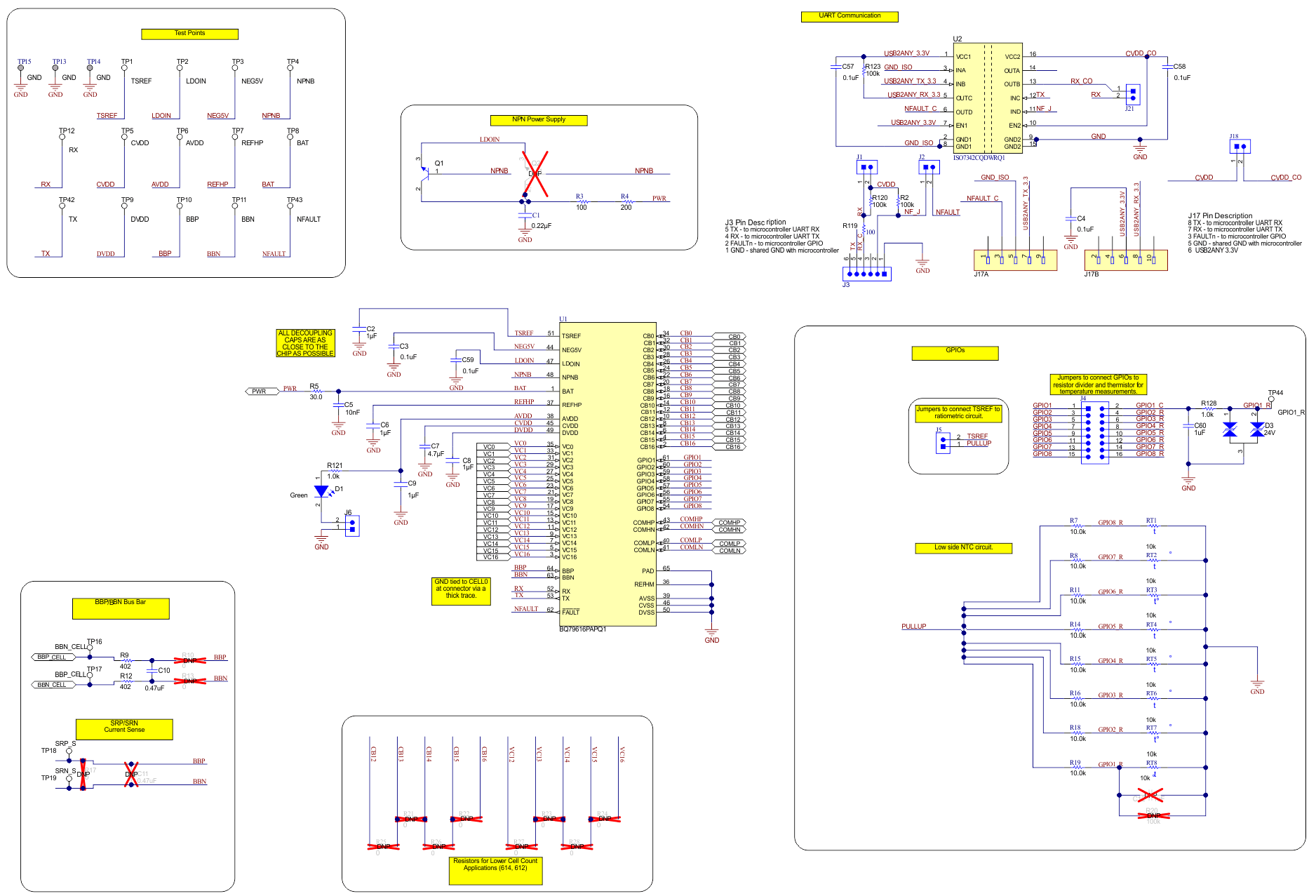
7.1 Schematic
 Figure 7-1 BQ79616EVM Schematic Block Diagram
 Figure 7-2 BQ79616EVM Schematic Part 1
 Figure 7-3 BQ79616EVM Schematic Part 2
 Figure 7-4 BQ79616EVM Schematic Part 3
 Figure 7-5 BQ79616EVM Schematic Part 4