SLUUC37C july 2019 – august 2023 BQ75614-Q1 , BQ79616 , BQ79616-Q1 , BQ79656-Q1
- 1
- BQ79616-Q1 and BQ75614-Q1 Evaluation Modules
- Trademarks
- General Texas Instruments High Voltage Evaluation (TI HV EVM) User Safety Guidelines
- 1 General Description
- 2 Theory of Operation - Stackable BQ79616EVM
- 3 Theory of Operation - Standalone BQ75614EVM
- 4 Connectors
- 5 Quick Start Guide
- 6 Physical Dimensions
- 7 BQ79616EVM Schematic, Assembly, Layout, and BOM
- 8 BQ75614EVM Schematic, Assembly, Layout, and BOM
- 9 BQ79656EVM Schematic, Assembly, Layout, and BOM
- 10Revision History
3 Theory of Operation - Standalone BQ75614EVM
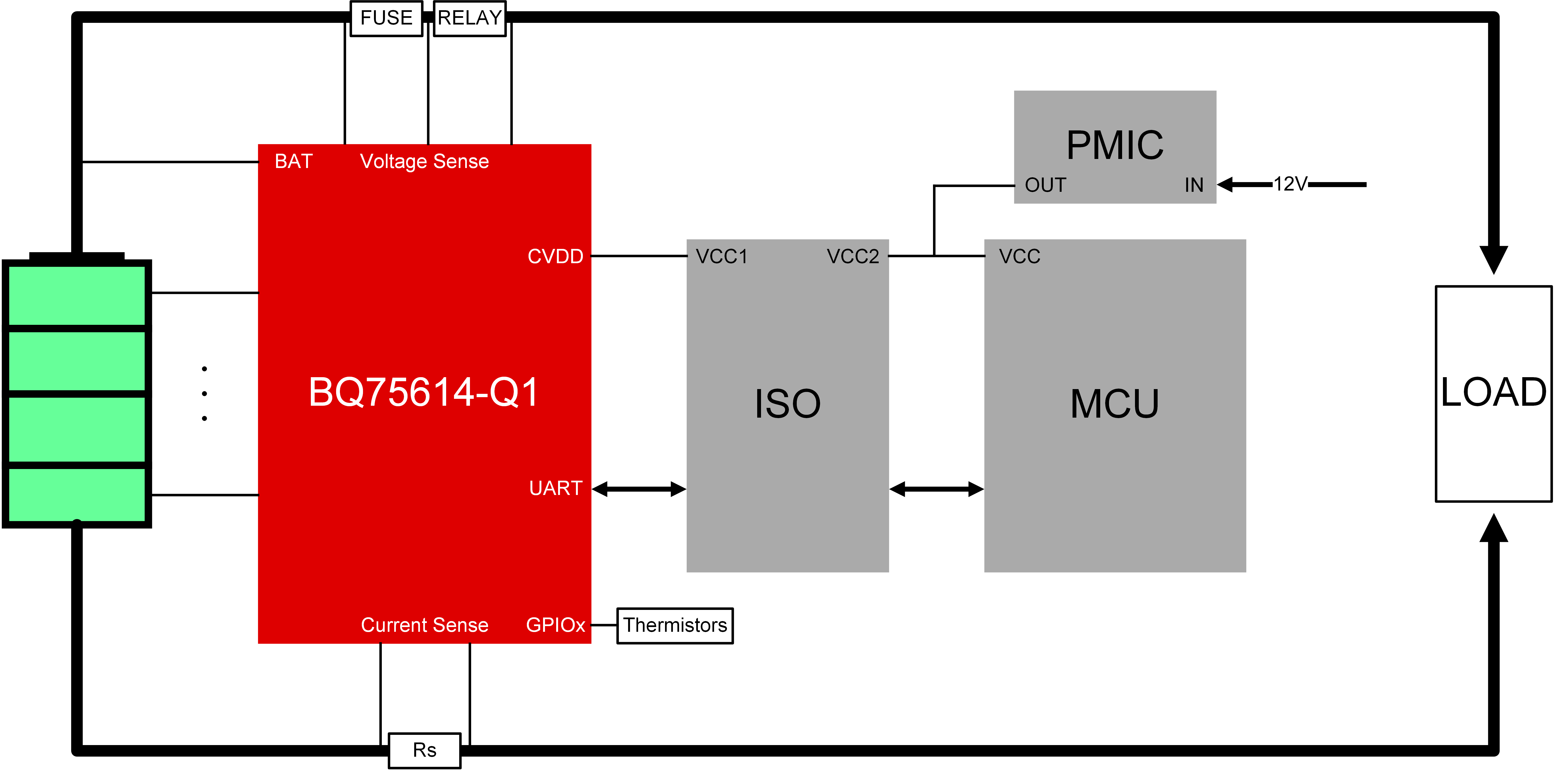
Figure 3-1 shows the system block diagram.
 Figure 3-1 System
Block Diagram - BQ75614
Figure 3-1 System
Block Diagram - BQ75614The BMS system is designed to prolong the useful life of lithium-ion cells in battery packs through passive balancing, and provide enhanced SOC and SOH measurements using integrated current sense measurement. The device can monitor a battery pack which contains up to 16 cells, or up to 14 cells with the ability to measure fuse and relay voltages. This system monitors voltages of individual battery cells and dissipates individual cell voltages through the use of internal cell balancing FETs. The BMS allows battery-powered electric machines to use smaller battery packs and fewer charging cycles to perform the same amount of work. The BMS also improves the overall lifetime of Li-ion battery packs by preventing undervoltage and overvoltage damage from occurring.
The typical BMS system with integrated current sense has two main sub-systems, as shown in Figure 3-1:
- Host controller - in this case a TMS570 LaunchPad™
- BQ75614EVM module attached to cells, and communicating with the host
- Optional: a digital isolator between the host domain and the BQ75614EVM domain
All commands and data are communicated with a host through UART. The BQ75614-Q1 remains idle until a command is received from the host. The BQ75614EVM can support a host PC or microcontroller (via the UART connection header).
The typical flow is for the host to go through the following simplified sequence:
- Wakeup the BQ75614EVM board by sending a WAKEUP pulse when using the UART interface.
- Send a sample command to the BQ75614-Q1 to read the cell measurement results and current measurement results.
- The host uses the cell measurement data to calculate an average and determine the highest or lowest cells and determine the cells that are balanced. The host uses the current measurement data to estimate SOC and SOH.
- If no stop command is sent, then the BQ75614-Q1 has a built-in timeout (set by the user), after which time the discharge is stopped automatically.
- The host can then decide to repeat the process (back to step 2) or send commands to shutdown the BQ75614EVM and return later.
As a single standalone board, the BQ75614EVM can passively balance up to 16 cells, up to 80 V of total voltage. Communication to the BQ75614EVM is handled by the UART host interface.