SLVAFU8 July   2024 TPSI2072-Q1 , TPSI2140-Q1 , TPSI3050 , TPSI3050-Q1 , TPSI3052 , TPSI3052-Q1 , TPSI3100 , TPSI3100-Q1


  1.   1
  2.   Abstract
  3.   Trademarks
  4. 1Introduction
  5. 2What Are Solid-State Relays?
    1. 2.1 History
      1. 2.1.1 Electromechanical Relays
      2. 2.1.2 Solid-State Relays
    2. 2.2 Isolation Technologies
      1. 2.2.1 Isolation Specifications
    3. 2.3 Relay Evolution
  6. 3Failure Mechanisms
    1. 3.1 Arcing in an Electromechanical Relay
    2. 3.2 Photo-degradation in Photo Relays
    3. 3.3 Partial Discharge
    4. 3.4 Time-Dependent Dielectric Breakdown in Capacitive and Inductive Isolation
  7. 4Electromechanical vs. Photo vs. Capacitive or Inductive
    1. 4.1 Electromechanical Relays
      1. 4.1.1 Advantages
        1. 4.1.1.1 No Leakage Current
      2. 4.1.2 Limitations
        1. 4.1.2.1 Switching Speed
        2. 4.1.2.2 Package Size
    2. 4.2 Photo or Optical Relays
      1. 4.2.1 Advantages
        1. 4.2.1.1 Lower EMI
      2. 4.2.2 Limitations
        1. 4.2.2.1 Limited Temperature Range
    3. 4.3 Capacitive or Inductive Based Relays
      1. 4.3.1 Advantages
        1. 4.3.1.1 Auxiliary Power
        2. 4.3.1.2 Bidirectional Communication
      2. 4.3.2 Limitations
        1. 4.3.2.1 EMI
    4. 4.4 Overall Comparison
  8. 5Summary
  9. 6References

Package Size

Electromechanical relays usually have larger heights than solid-state relays. This is because the the package needs to accommodate space for all of the parts within the device, such as the metal contacts, coil, and spring.

Figure 4-2 compares the package size of an electromechanical relay and an isolated switch driver.
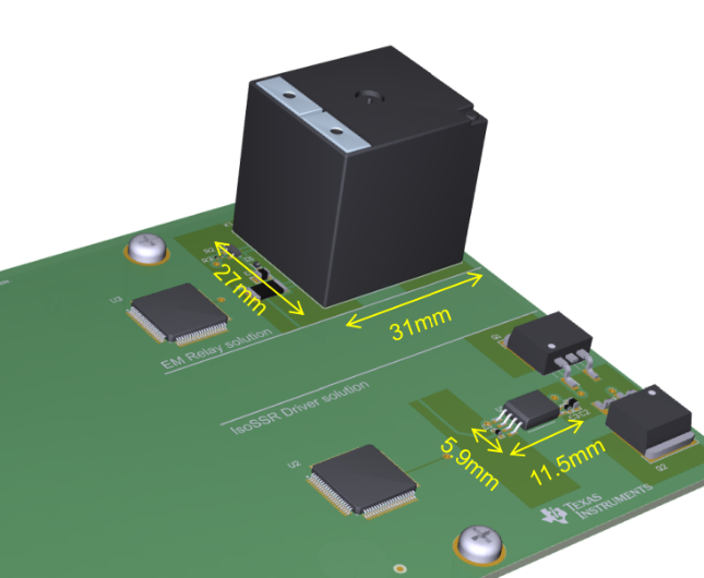
 Electromechanical Relay's
                    Package Size Figure 4-2 Electromechanical Relay's Package Size