SNLA461 July 2024 DS320PR1601 , DS320PR410 , DS320PR810 , SN75LVPE5412 , SN75LVPE5421
4 Over-Equalization and Redriver Placement
A redriver performs best when compensating for degradation that has already happened to an incoming signal by the time it enters the redriver's RX inputs. In this situation, the redriver only needs to boost the degraded frequency content back to normal levels. If there is not much loss behind the redriver, the final receiver can see a good quality signal.
Sometimes, a redriver can be placed in a situation where the incoming signal has minimal degradation, and instead there is a relatively large amount of loss behind the redriver that still requires compensation. In this case, the redriver can try to preemptively compensate for the loss behind the redriver by over-equalizing the signal—meaning that the high frequency content is boosted above normal levels—with the expectation that the post-redriver channel loss can naturally roll off the excess by the time the signal reaches the final receiver.
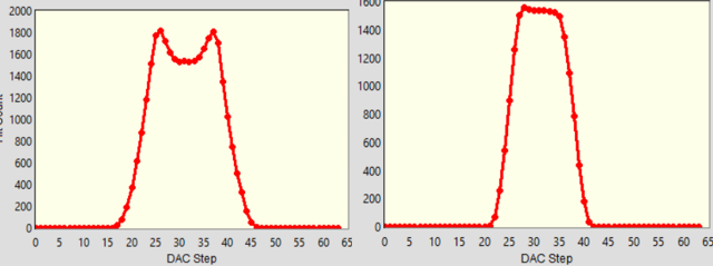
Over-equalization produces visible distortions of the signal, typically as exaggerated edges, that can be seen on an oscilloscope or through the Eye Scan feature of TI Gen 5 redrivers. Figure 4-1 shows an example of how over-equalization can be seen in Eye Scan: the over-equalized signal on the left panel has characteristic "horns" on the sides of the peak and a smaller flat region compared to the signal on the right panel that was provided a more normal amount of equalization. For more details on Eye Scan, refer to the Eye Scan With TI PCI- Express Gen5.0 Redrivers application note.
 Figure 4-1 Eye Scan Plot of Over-Equalized and Normal Signal
This method of preemptive compensation can often be used successfully with small amounts of over-equalization, but caution is warranted: for a number of reasons, over-equalizing a signal is not as clean of a process as applying a normal amount of equalization to a degraded signal. The amplifiers in the device can have difficulty operating in the linear region when applying excess amounts of equalization, resulting in compression or clipping effects similar to those seen in overdriven audio signals. Thus, high amounts of over-equalization can result in distortion that does not properly roll off, reducing the signal quality seen by the final receiver.
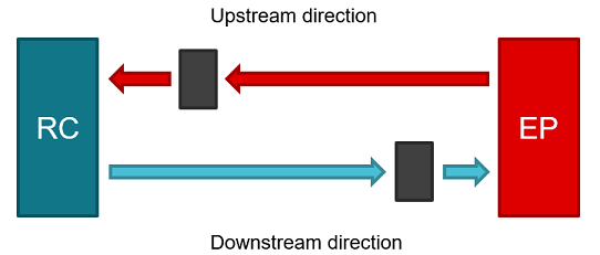
Because of this asymmetry in the performance of equalization compared to over-equalization, careful placement can contribute to the successful use of redrivers in a system. Unidirectional redrivers that handle upstream and downstream directions with separate devices can be placed at different locations; the downstream redrivers can be placed closer to the endpoint, and the upstream redrivers can be placed closer to the root complex. This way, redrivers for both directions have the majority of the loss front-loaded for best performance.
 Figure 4-2 Unidirectional Redriver Placement
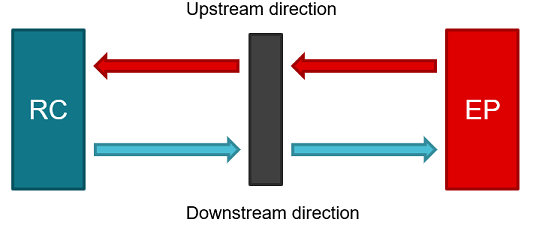
Bidirectional redrivers that handle both upstream and downstream directions in one device can be placed in the middle of the loss channel so that both directions can have similar performance. Otherwise, one direction can encounter more problems with over-equalization than the other. Some systems can have inherently different performance in the upstream and downstream directions due to varying TX and RX performance by the root complex and endpoint; if this is the case, an off-center placement of a bidirectional redriver can be beneficial if supported by simulation results and past experience. Note that in a bidirectional redriver, it is still possible to configure the EQ settings separately for each direction as needed.
 Figure 4-3 Bidirectional Redriver Placement
Signal integrity simulations using device IBIS-AMI or S-parameter models can be used to help evaluate redriver placement in the early stages of board layout design by distributing the total link loss in different amounts before and after the redriver, and checking the behavior of both directions. After architecture and space constraints are accounted for and the final placement is selected, the next step is to carefully design the PCB layout to reduce signal impairments and provide as much performance margin for the redriver as possible. For more details, refer to the High-Speed PCB Layout for PCIe Gen 5 application note.