SPRAC94D September 2018 – March 2022 AFE030 , AFE031 , TMS320F28075 , TMS320F28075-Q1 , TMS320F28076 , TMS320F28374D , TMS320F28374S , TMS320F28375D , TMS320F28375S , TMS320F28375S-Q1 , TMS320F28376D , TMS320F28376S , TMS320F28377D , TMS320F28377D-EP , TMS320F28377D-Q1 , TMS320F28377S , TMS320F28377S-Q1 , TMS320F28379D , TMS320F28379D-Q1 , TMS320F28379S
- Trademarks
- 1 FSK Overview
- 2 Hardware Overview
- 3 Interfacing With the AFE03x
- 4 Transmit Path
- 5 Receive Path
- 6 Interfacing With a Power Line
- 7 Summary
- 8 References
- 9 Schematics
- 10Revision History
4.2 PWM Mode
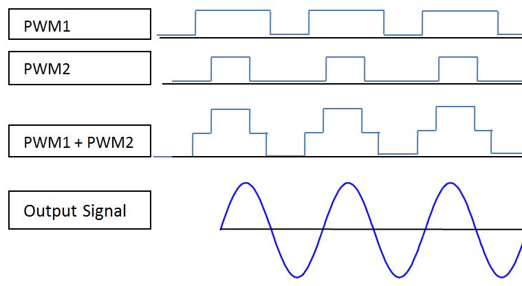
In PWM mode, the C2000 F28379D generates two symmetric PWM signals that go directly into the AFE device. The two symmetric PWM signals are 66% and 33% duty cycle. These signals are added together inside the AFE device and create a waveform that has the least amount of noise. Figure 4-1 shows how this addition works.
 Figure 4-1 PWM Addition
The path of the PWM signals is shown in Figure 4-2. The PWM signals go into the low-pass filter internal to the AFE030/1 device, and are added together to create the above PWM1+PWM2 waveform.
 Figure 4-2 PWM Transmit Path
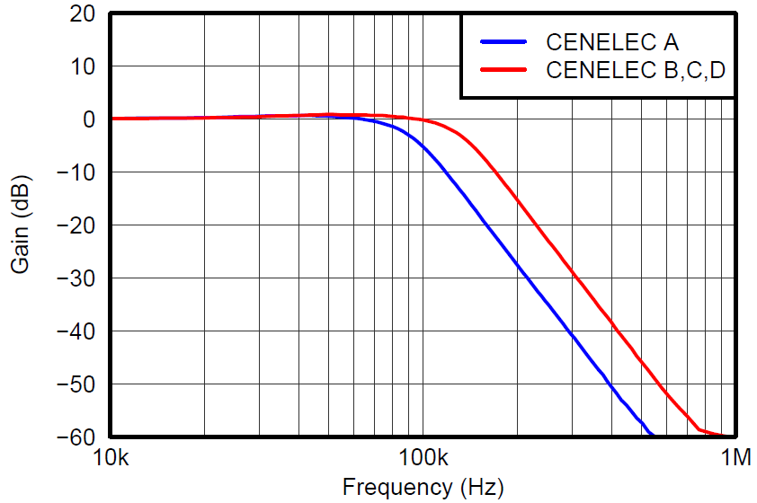
The gains witnessed at certain frequencies at the output of the internal TX low-pass filter are shown in Figure 4-3.
 Figure 4-3 TX Filter Gain vs. Frequency
Next, the signal goes through a low-pass filter, PGA, another low-pass filter, and finally out of the PA. The external low-pass filters can be tuned to filter the desired frequencies shown in Table 4-2.
| Frequency Band | R (Ω) | C (nF) |
|---|---|---|
| SFSK: 63 kHz, 74 kHz | 510 | 2.7 |
| CENELEC A | 510 | 1.5 |
| CENELEC B,C,D | 510 | 1 |