SPRACW5A April 2021 – December 2021 F29H850TU , F29H859TU-Q1 , TMS320F2800132 , TMS320F2800133 , TMS320F2800135 , TMS320F2800137 , TMS320F280021 , TMS320F280021-Q1 , TMS320F280023 , TMS320F280023-Q1 , TMS320F280023C , TMS320F280025 , TMS320F280025-Q1 , TMS320F280025C , TMS320F280025C-Q1 , TMS320F280033 , TMS320F280034 , TMS320F280034-Q1 , TMS320F280036-Q1 , TMS320F280036C-Q1 , TMS320F280037 , TMS320F280037-Q1 , TMS320F280037C , TMS320F280037C-Q1 , TMS320F280038-Q1 , TMS320F280038C-Q1 , TMS320F280039 , TMS320F280039-Q1 , TMS320F280039C , TMS320F280039C-Q1 , TMS320F280040-Q1 , TMS320F280040C-Q1 , TMS320F280041 , TMS320F280041-Q1 , TMS320F280041C , TMS320F280041C-Q1 , TMS320F280045 , TMS320F280048-Q1 , TMS320F280048C-Q1 , TMS320F280049 , TMS320F280049-Q1 , TMS320F280049C , TMS320F280049C-Q1 , TMS320F28075 , TMS320F28075-Q1 , TMS320F28076 , TMS320F28374D , TMS320F28374S , TMS320F28375D , TMS320F28375S , TMS320F28375S-Q1 , TMS320F28376D , TMS320F28376S , TMS320F28377D , TMS320F28377D-EP , TMS320F28377D-Q1 , TMS320F28377S , TMS320F28377S-Q1 , TMS320F28378D , TMS320F28378S , TMS320F28379D , TMS320F28379D-Q1 , TMS320F28379S , TMS320F28384D , TMS320F28384D-Q1 , TMS320F28384S , TMS320F28384S-Q1 , TMS320F28386D , TMS320F28386D-Q1 , TMS320F28386S , TMS320F28386S-Q1 , TMS320F28388D , TMS320F28388S , TMS320F28P650DH , TMS320F28P650DK , TMS320F28P650SH , TMS320F28P650SK , TMS320F28P659DH-Q1 , TMS320F28P659DK-Q1 , TMS320F28P659SH-Q1
- Trademarks
- 1Introduction
- 2ACI Motor Control Benchmark Application
- 3Real-time Benchmark Data Analysis
-
4C2000 Value Proposition
- 4.1 Efficient Signal Chain Execution With Better Real-Time Response Than Higher Computational MIPS Devices
- 4.2 Excellent Real-Time Interrupt Response With Low Latency
- 4.3 Tight Peripheral Integration That Scales Applications With Large Number of Peripheral Accesses
- 4.4 Best in Class Trigonometric Math Engine
- 4.5 Versatile Performance Boosting Compute Engine (CLA)
- 4.6 Deterministic Execution due to Low Execution Variance
- 5Summary
- 6References
- 7Revision History
2.5.1 Details of Benchmarking With Counters
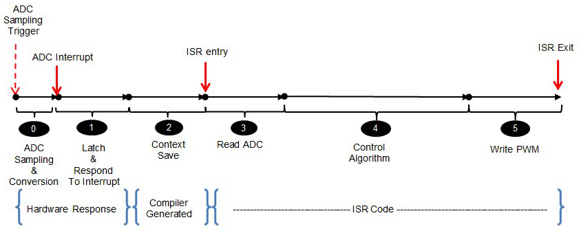
Real-time benchmarking requires measuring performance along different phases of the signal chain. As indicated in Figure 2-4, this can be largely broken up into three parts: hardware response, compiler generated context save and user code inside the interrupt service routine(ISR).
 Figure 2-4 Real-Time Benchmarking
Phases
Figure 2-4 Real-Time Benchmarking
PhasesMeasuring execution inside the ISR is a straightforward task. The timer peripheral can be used to benchmark code inside the ISR by inserting pieces of code that read the timer counter before and after a block of code and calculating the difference. The application measures the control code and the ADC read and PWM writes using this method. This approach however is not possible for the compiler generated context save and for the hardware response measurement.
In this particular application, the PWM is used to trigger ADC sampling when the PWM counter reaches a certain value (timebase period) and the ADC in turn generates an interrupt when sampling completes. While it is not possible to measure the hardware response and the compiler generated context save separately, they can be measured together by reading the PWM counter as the first operation inside the ISR code and calculating the difference between the PWM value read and the PWM value when ADC sampling was triggered. This is the method by which the application measures the INT response (hardware response + compiler context save).