TIDUF32 December   2024 ADC128S102QML-SP , INA901-SP , LM117QML-SP , LM193QML-SP , LM4050QML-SP , LMP7704-SP , MSP430FR5969-SP , TMP9R00-SP , TPS7A4501-SP , TPS7H2211-SP , TPS7H5001-SP , TPS7H6003-SP


  1.   1
  2.   Description
  3.   Resources
  4.   Features
  5.   Applications
  6.   6
  7. 1System Description
  8. 2System Overview
    1. 2.1 Block Diagram
    2. 2.2 Design Considerations
      1. 2.2.1 System Control and Processing
      2. 2.2.2 Battery Cell Monitoring
      3. 2.2.3 Temperature Sensing
      4. 2.2.4 Battery Stack Control
      5. 2.2.5 Battery Balancing
      6. 2.2.6 Power Tree and Power Sequencing
    3. 2.3 Highlighted Products
      1. 2.3.1  MSP430FR5969-SP
      2. 2.3.2  ADC128S102QML-SP
      3. 2.3.3  TLV1H103-SEP
      4. 2.3.4  TPS7H2211-SP
      5. 2.3.5  TPS7A4501-SP
      6. 2.3.6  INA901-SP
      7. 2.3.7  INA1H94-SP
      8. 2.3.8  LMP7704-SP
      9. 2.3.9  TMP9R00-SP
      10. 2.3.10 LM117QML-SP
      11. 2.3.11 LM4050QML-SP
  9. 3Hardware, Software, Testing Requirements, and Test Results
    1. 3.1 Hardware Requirements
    2. 3.2 Software Requirements
    3. 3.3 Test Setup
    4. 3.4 Test Results
  10. 4Design and Documentation Support
    1. 4.1 Design Files
      1. 4.1.1 Schematics
      2. 4.1.2 BOM
    2. 4.2 Tools and Software
    3. 4.3 Documentation Support
    4. 4.4 Support Resources
    5. 4.5 Trademarks
  11. 5About the Author

Test Results

Figure 3-3 illustrates the battery cell monitoring error after offset calibration. Error is less than ±1mV for battery voltages ranging from 3.0V to 4.2V.
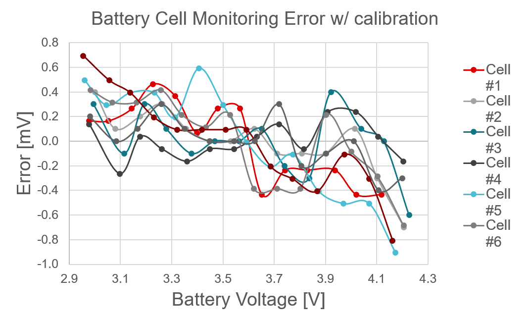
TIDA-010931 Battery Cell Monitoring ErrorFigure 3-3 Battery Cell Monitoring Error

Figure 3-4 shows the short-circuit protection with power turned off within a 4.56μs delay.
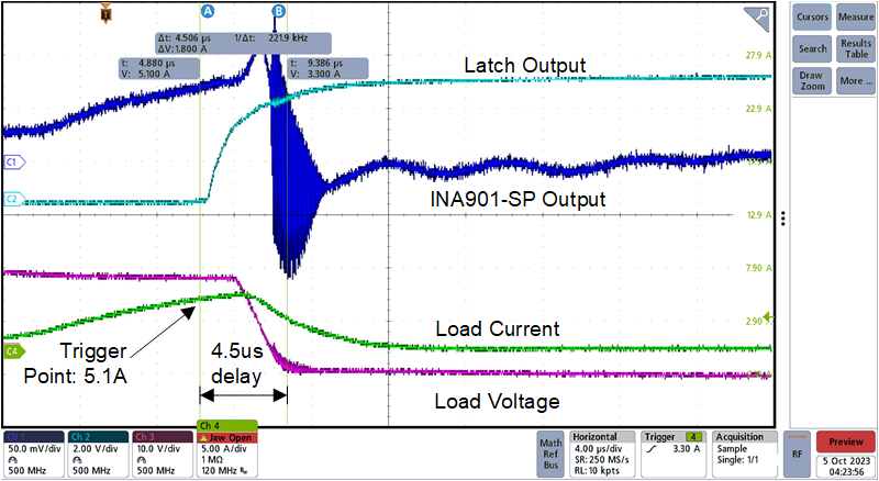
TIDA-010931 Short-Circuit ProtectionFigure 3-4 Short-Circuit Protection