-
Tuning Lead Angle in DRV10x Sensorless BLDC Drivers
Tuning Lead Angle in DRV10x Sensorless BLDC Drivers
Trademarks
All trademarks are the property of their respective owners.
1 Introduction
Lead angle, also known as Commutation control advance angle is the angle between phase voltage applied to the motor and the Motor BEMF voltage. Figure 1-1 shows the basic motor model. R and L are the resistance and inductance of the stator windings of the motor.
 Figure 1-1 BLDC Motor model
Because of the inductance of the motor, phase current of the motor lags phase voltage applied to the motor as shown in Figure 1-2 and Figure 1-3. As a result, the BEMF voltage gets misaligned with phase current. When phase current is not aligned with BEMF voltage, the power drawn by the motor does not get fully utilized to generate torque resulting in poor power efficiency of the motor-driver system. To address this issue, DRV10x sensorless motor drivers provide configuration bits to advance the phase voltage applied to the motor and align the motor phase current with the motor BEMF voltage. Lead angle is expected to be lower for lower inductance motors and higher for inductance motors.
Phase difference between the phase to phase voltage and BEMF voltage is lead angle. In Figure 1-2, the phase current is not aligned with motor BEMF voltage. At this lead angle, the efficiency is expected to be poor. In Figure 1-3, the phase current is aligned with motor BEMF voltage by advancing the phase voltage applied to the motor. At this lead angle, the efficiency is optimized.
 Figure 1-2 Phase current is
un-aligned with BEMF voltage Lead angle is not optimized
 Figure 1-3 Phase current is aligned
with BEMF voltage Lead angle is optimized
Figure 1-3 Phase current is aligned
with BEMF voltage Lead angle is optimized2 Concept
BLDC motors operate efficiently when the stator magnetic flux and rotor magnetic flux are in quadrature alignment (90°). To achieve this 90° angle between the stator and rotor flux, the BEMF voltage must be aligned with the phase current.
This alignment between the BEMF voltage and phase current can be achieved by adjusting the lead angle. It is important to know the target speed or torque of the motor because with variation in speed or torque, the BEMF voltage and phase current get misaligned for a fixed lead angle. Lead angle must be adjusted when an operating condition, such as speed and load, is changed to operate the motor at optimal efficiency. At the target speed, when the BEMF voltage and phase current are aligned, the motor draws least amount of phase current and the efficiency is optimized.
Below are the steps to tune lead angle:
- While operating in closed loop, set the speed command to achieve the desired operating speed where the efficiency needs to be optimized.
- Sweep the lead angle around the
programmed lead angle and measure the motor phase current (rms) and motor speed (Hz)
for each value of lead angle. It is recommended to measure the motor speed by
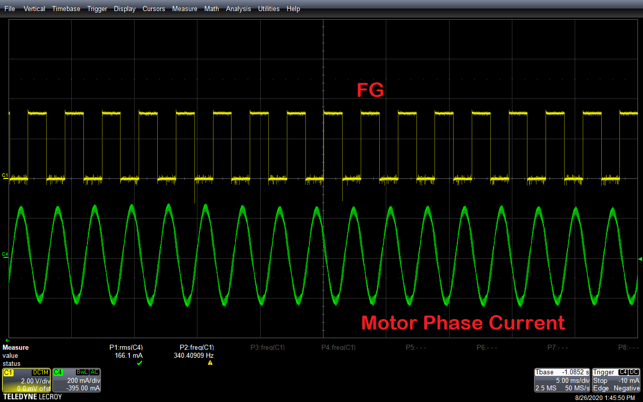
measuring the frequency of FG signal for accurate results. Figure 2-1 shows the phase current and FG plot. Measure the RMS value of phase current and
frequency of FG signal.
 Figure 2-1 FG and Phase
current
 - Calculate the ratio of phase current over motor speed. Optimum efficiency is achieved at the lead angle where the ratio of phase current over speed is lowest. At this point, the estimated BEMF will be almost equal to programmed/measured BEMF of the motor.
Here is an example of tuning lead angle for a sample BLDC motor.
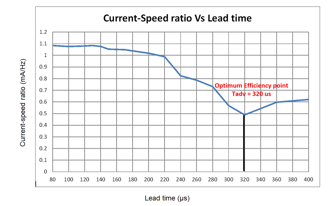
Rated speed of the sample motor is 340 Hz (Electrical Speed). Speed command is set to 100% duty cycle as the efficiency needs to be optimized at 340 Hz. Table 2-1 shows the experimental phase current, speed and their ratio after sweeping the lead time from 80 µs to 400 µs. DRV10x takes lead time as input and converts lead time to lead angle. Data points in Table 2-1 are plotted in Figure 2-2. Figure 2-2 shows the current-speed ratio Vs Lead time.
| Lead time (µs) | Phase current (mA) | Speed (Hz) | Phase current/Speed (mA/Hz) |
|---|---|---|---|
| 80 | 326.6 | 301.3 | 1.084 |
| 100 | 324.2 | 301.2 | 1.076 |
| 120 | 325.4 | 301.2 | 1.080 |
| 130 | 326.7 | 301.4 | 1.084 |
| 140 | 325.5 | 302.3 | 1.077 |
| 150 | 319.1 | 303.1 | 1.053 |
| 170 | 317.0 | 302.2 | 1.049 |
| 200 | 310.5 | 305 | 1.018 |
| 220 | 302.4 | 306 | 0.988 |
| 240 | 260.2 | 315.6 | 0.824 |
| 260 | 250.3 | 318 | 0.787 |
| 280 | 235.6 | 322 | 0.732 |
| 300 | 191.0 | 335.9 | 0.569 |
| 320 | 166.1 | 340 | 0.489 |
| 360 | 237.7 | 398 | 0.597 |
| 400 | 251.0 | 403 | 0.623 |
 Figure 2-2 Current-Speed ratio Vs Lead
time
Figure 2-2 Current-Speed ratio Vs Lead
timeThe lowest current-speed ratio is achieved at 320 µs. At this operating point, minimum load current is drawn by the motor. This will be the optimum efficiency point at 340 Hz. Above 320 us we see the speed and phase current increasing rapidly. This is because the motor is in the field weakening region where the rotor magnetic flux gets weakened with increase in phase current and motor speed increases above the rated speed. It is not recommended to operate DRV10x devices in field weakening region for applications sensitive to acoustic noise because the phase current might be distorted and can also reduce the life span of the motor.
3 References
For additional references, refer to the following.
- Texas Instruments, Adaptive Drive Angle Adjust
- Texas Instruments, DRV10987 Tuning Guide
- Texas Instruments, DRV10974 Tuning Guide
IMPORTANT NOTICE AND DISCLAIMER
| TI PROVIDES TECHNICAL AND RELIABILITY DATA (INCLUDING DATASHEETS), DESIGN RESOURCES (INCLUDING REFERENCE DESIGNS), APPLICATION OR OTHER DESIGN ADVICE, WEB TOOLS, SAFETY INFORMATION, AND OTHER RESOURCES “AS IS” AND WITH ALL FAULTS, AND DISCLAIMS ALL WARRANTIES, EXPRESS AND IMPLIED, INCLUDING WITHOUT LIMITATION ANY IMPLIED WARRANTIES OF MERCHANTABILITY, FITNESS FOR A PARTICULAR PURPOSE OR NON-INFRINGEMENT OF THIRD PARTY INTELLECTUAL PROPERTY RIGHTS. |
| These resources are intended for skilled developers designing with TI products. You are solely responsible for (1) selecting the appropriate TI products for your application, (2) designing, validating and testing your application, and (3) ensuring your application meets applicable standards, and any other safety, security, or other requirements. These resources are subject to change without notice. TI grants you permission to use these resources only for development of an application that uses the TI products described in the resource. Other reproduction and display of these resources is prohibited. No license is granted to any other TI intellectual property right or to any third party intellectual property right. TI disclaims responsibility for, and you will fully indemnify TI and its representatives against, any claims, damages, costs, losses, and liabilities arising out of your use of these resources. |
| TI’s products are provided subject to TI’s Terms of Sale (www.ti.com/legal/termsofsale.html) or other applicable terms available either on ti.com or provided in conjunction with such TI products. TI’s provision of these resources does not expand or otherwise alter TI’s applicable warranties or warranty disclaimers for TI products. |
| Mailing Address: Texas Instruments, Post Office Box 655303, Dallas, Texas 75265
Copyright © 2020, Texas Instruments Incorporated |