SBOA615 November 2024 INA180 , INA180-Q1 , INA181 , INA181-Q1 , INA183 , INA185 , INA185-Q1 , INA186 , INA186-Q1 , INA190 , INA190-EP , INA190-Q1 , INA191 , INA199 , INA199-Q1 , INA209 , INA210 , INA210-Q1 , INA211 , INA211-Q1 , INA212 , INA212-Q1 , INA213 , INA213-Q1 , INA214 , INA214-Q1 , INA215 , INA215-Q1 , INA216 , INA2180 , INA2180-Q1 , INA2181 , INA2181-Q1 , INA219 , INA2191 , INA220 , INA220-Q1 , INA223 , INA225 , INA225-Q1 , INA226 , INA226-Q1 , INA228 , INA228-Q1 , INA229 , INA229-Q1 , INA2290 , INA230 , INA231 , INA232 , INA233 , INA234 , INA236 , INA237 , INA237-Q1 , INA238 , INA238-Q1 , INA239 , INA239-Q1 , INA240 , INA240-Q1 , INA241A , INA241A-Q1 , INA241B , INA241B-Q1 , INA250 , INA250-Q1 , INA253 , INA253-Q1 , INA254 , INA260 , INA280 , INA280-Q1 , INA281 , INA281-Q1 , INA290 , INA290-Q1 , INA293 , INA293-Q1 , INA296A , INA296A-Q1 , INA296B , INA296B-Q1 , INA300 , INA300-Q1 , INA301 , INA301-Q1 , INA302 , INA302-Q1 , INA303 , INA303-Q1 , INA310A , INA310A-Q1 , INA310B , INA310B-Q1 , INA3221 , INA3221-Q1 , INA381 , INA381-Q1 , INA4180 , INA4180-Q1 , INA4181 , INA4181-Q1 , INA4230 , INA4235 , INA4290 , INA700 , INA740A , INA740B , INA745A , INA745B , INA750B , INA780A , INA780B , INA790B , INA791B , LMP8278Q-Q1 , LMP8601 , LMP8601-Q1 , LMP8602 , LMP8602-Q1 , LMP8603 , LMP8603-Q1 , LMP8640 , LMP8640-Q1 , LMP8640HV
- 1
- Abstract
- Trademarks
- 1Introduction
- 2What is ESD, EOS, and Latch Up?
- 3Risky Applications for Current Sense Amplifiers
- 4Summary
- 5References
3.3.1.1 Techniques for Proper Grounding and Decoupling Capacitance
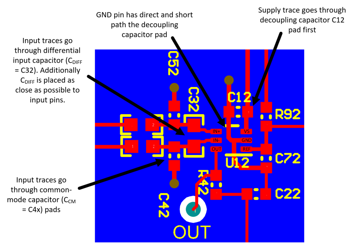
- GND pin has a low-impedance, direct path to the decoupling capacitor pad.
- There is low-impedance, direct path from decoupling ground pad to system ground pour.
- The supply trace for supply pin (VS) must go through decoupling capacitor.
Figure 3-3 is an example with proper layout for filters at both supply and input pins on a standard CSA. C12 is the standard 0.1μF decoupling capacitor.
 Figure 3-3 Good Decoupling Capacitor
Layout
Figure 3-3 Good Decoupling Capacitor
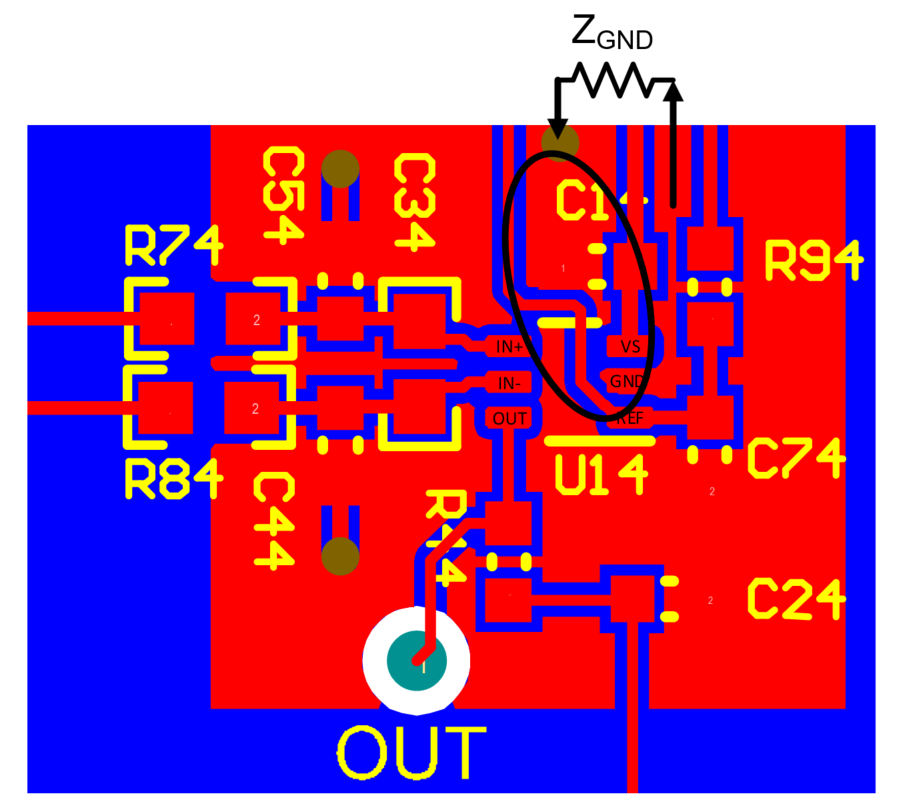
LayoutFigure 3-4 shows bad layout where there is significant impedance in between GND pin and decoupling capacitor making this device susceptible to latch up in EMI environments.
 Figure 3-4 Bad Decoupling Capacitor
Layout With Impedance from Pin to Capacitor