SLAAE58 april 2023 MSPM0G1105 , MSPM0G1106 , MSPM0G1107 , MSPM0G1505 , MSPM0G1506 , MSPM0G1507 , MSPM0G3105 , MSPM0G3106 , MSPM0G3107 , MSPM0G3505 , MSPM0G3506 , MSPM0G3507 , MSPM0L1105 , MSPM0L1106 , MSPM0L1303 , MSPM0L1304 , MSPM0L1304-Q1 , MSPM0L1305 , MSPM0L1305-Q1 , MSPM0L1306 , MSPM0L1306-Q1 , MSPM0L1343 , MSPM0L1344 , MSPM0L1345 , MSPM0L1346
2 Implementation
Principle
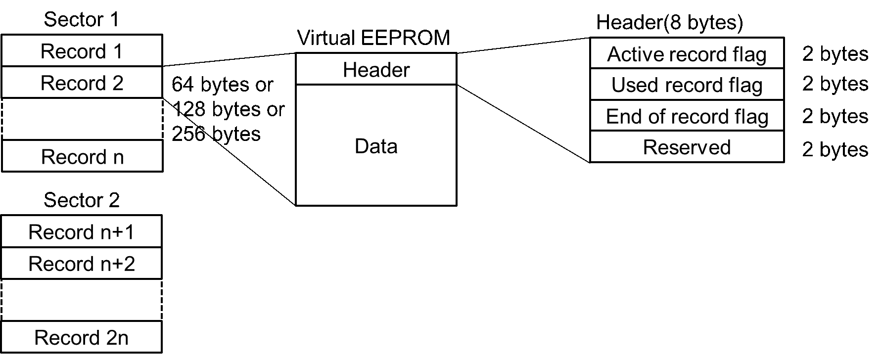
In the implementation described in this app note, sectors are divided into areas called 'records' according to the size of the virtual EEPROM. Each record contains header and data. Header shows the status of the record. The remainder of the record (total record size minus the 8-byte size of the header) is used for storing user data. The number of records in one sector is (SectorSize / RecordSize). For 128-bytes record size, there are 8 records in one sector. Figure 2-1shows the structure of EEPROM emulation.
All of these records are used to store data of the same virtual EEPROM. When trying to modify the data of the virtual EEPROM, a new record is actually created instead of being modified on the original record. The difference between records in Flash is whether the data is new or old. In other word, they are different versions of the same data. It is more like a backup for memory area in RAM.
There are three user-configurable parameters, which can be configured in eeprom_emulation_type_a.h due to the application requirements. These parameters affect space usage and cycling capability, which will be analyzed later.
- Record size: 64 bytes or 128bytes or 256bytes
- Number of sectors used: at least 2
- Sector address
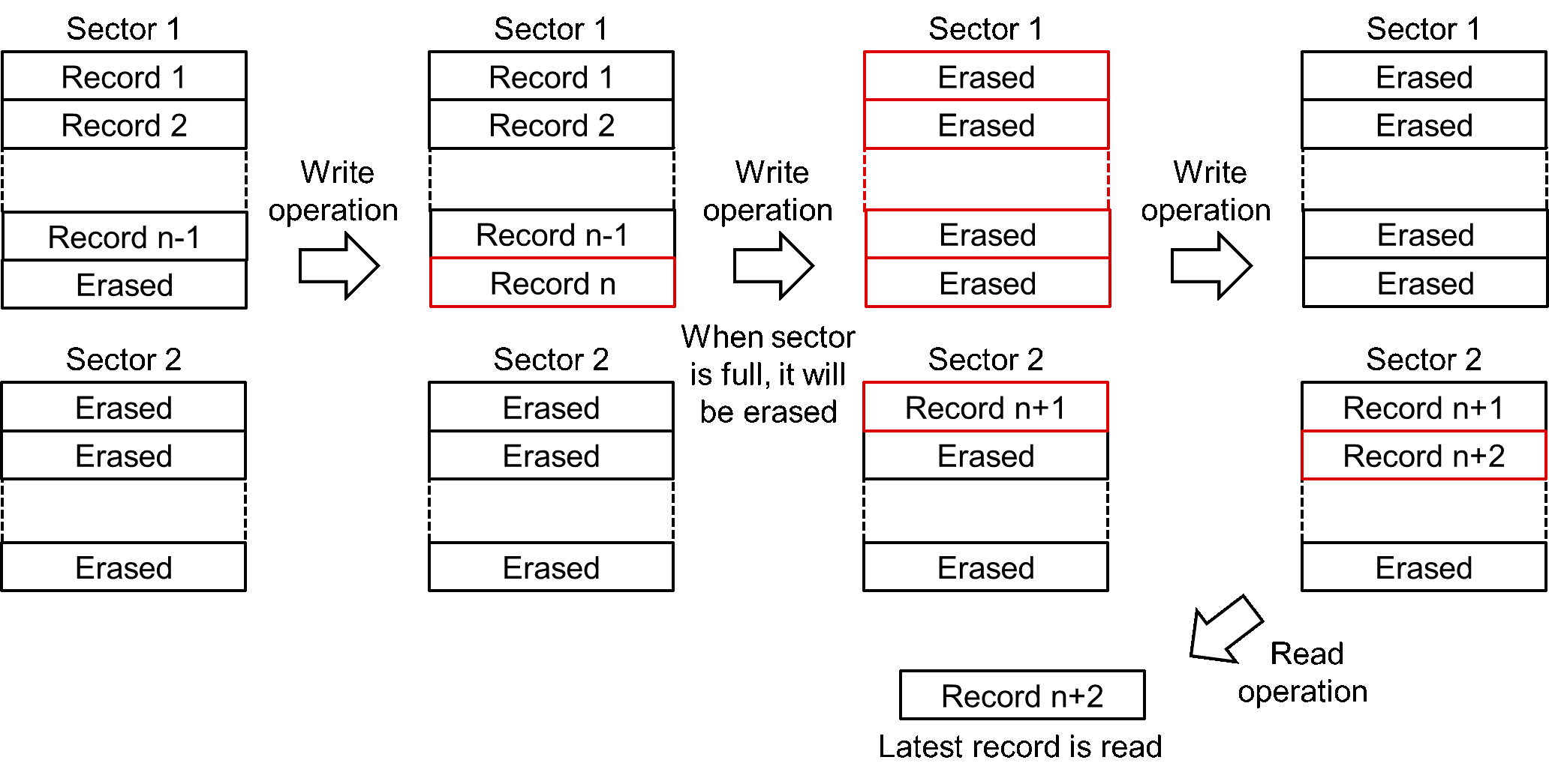
The basic behaviors of EEPROM emulation can be seen in Figure 2-2. When write operation is performed, user’s data is stored into Flash to be a new record. When read operation is performed, the latest record is read. The erase operation is performed only when the sector is full.
 Figure 2-1 Structure of EEPROM Emulation
 Figure 2-2 Basic Behaviors of EEPROM Emulation
Header
The header is designed to manage the record. By checking the header of a single record, the status of the record can be determined. By checking the headers of all records, the latest record can be found and the format of EEPROM emulation can be checked.
Each record has a header to show its status. The header is set to 8 bytes with 3 flags. Depending on the flags, there are four record status in total. The relationship between flags and record status is showed below.
| Record Status | Active Record Flag | Used Record Flag | End of Record Flag |
|---|---|---|---|
| Erased | 0xFFFF | 0xFFFF | 0xFFFF |
| Recording | 0x0000 | 0xFFFF | 0xFFFF |
| Active (latest) | 0x0000 | 0xFFFF | 0x0000 |
| Used (Not latest) | 0x0000 | 0x0000 | 0x0000 |
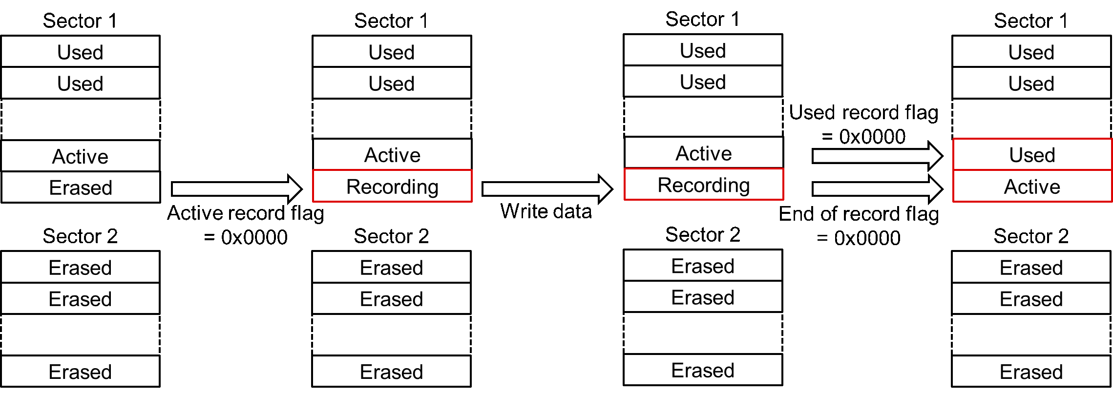
All flags are erased at first. When a new record is written, firstly active record flag is set and the status change to ‘Recording’. Then the data is written to the record. The end of record flag is set only when the data is completely written. It monitors the completion of the write operation. If the system loses power while writing data, it will be detected on recovery that record status is ‘Recording’.
After a new active record appearing, the old active record then changes to ‘Used’ by setting used record flag. Figure 2-3 shows how record status change when write operation is performed. It can be seen that there is always an active record, which helps to recover from power off.
 Figure 2-3 How Record Status Changes When Write Operation is Performed