SLAAEB4 april 2023 MSPM0G1105 , MSPM0G1106 , MSPM0G1107 , MSPM0G1505 , MSPM0G1506 , MSPM0G1507 , MSPM0G3105 , MSPM0G3106 , MSPM0G3107 , MSPM0G3505 , MSPM0G3506 , MSPM0G3507 , MSPM0L1105 , MSPM0L1106 , MSPM0L1303 , MSPM0L1304 , MSPM0L1304-Q1 , MSPM0L1305-Q1 , MSPM0L1306 , MSPM0L1306-Q1 , MSPM0L1343 , MSPM0L1344 , MSPM0L1345 , MSPM0L1346
2.1 Principle
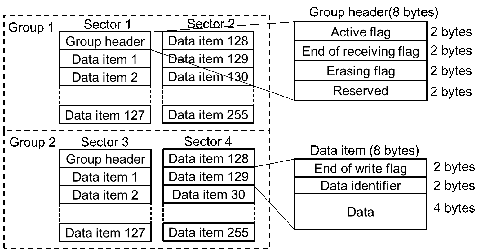
In the solution of this article, Flash are divided into areas which called data item. Each data item is 8 bytes, containing data, end-of-write flag and identifier. Identifier is used to identify and distinguish data, similar to variable name or virtual address. Two data items in flash can have the same identifier, but only the most recent data item is valid. Since data items are written sequentially, old and new data items can be distinguished based on position.
When a read operation is performed, the corresponding data item is found based on the identifier. If there are multiple data items with the same identifier, only the latest data item is valid. When a write operation is performed, data and identifiers are input, and assembled as new data item. Therefore, when the user wants to update the data item corresponding to an identifier, the write operation does not modify the previous data item, but continues to create new data item in the unused area. Typically, if the sector is full, the most recent data item corresponding to each identifier is transferred to the next sector, and the sector is then erased. As an extreme example, when the user only updates the data corresponding to a certain identifier, after the sector is full, the identifiers of all data items are the same, and the transfer operation will only transfer the last data item.
It should be noted that since the sector size is fixed, the number of data items that a single sector can hold is limited and fixed. To store more data items, sectors are grouped into group. Sectors in the same group will be erased together. When a group is full, the latest data items will be transferred to next group, and this group will be erased then. Figure 2-1 shows the structure of EEPROM emulation.
To mark the status of the group, the first 8 bytes of the group are used as the header. The remainder of the group (total group size minus the 8-byte size of the header) is used for storing data items. The number of data items in one sector is (SectorSize × Number of Sectors in One Group / DataItemSize - 1). For example, if one group has 1 sector, it can store 127 data items. If one group has 2 sectors, it can store 255 data items. If one group has 3 sectors, it can store 383 data items.
It should be emphasized that although users can use as many different identifiers as possible (at most equal to the number of data items), this might lead to frequent transfer operations and erase operations, which might lead to increased system overhead. The recommended number of identifiers is one-half to one-third of the maximum number of data items.
There are three user-configurable parameters, which can be configured in eeprom_emulation_type_b.h due to the application requirements. These parameters affect maximum number of data items and cycling capability, which will be analyzed later.
- Number of groups: at least 2
- Number of sectors in one group: at least 1
- Sector address
Additionally, in the structure of data item, end-of-write flag is used to ensure the write integrity of data items. The flag is set to 0x0000 after the data and identifier are written.
 Figure 2-1 The Structure of EEPROM
Emulation
Figure 2-1 The Structure of EEPROM
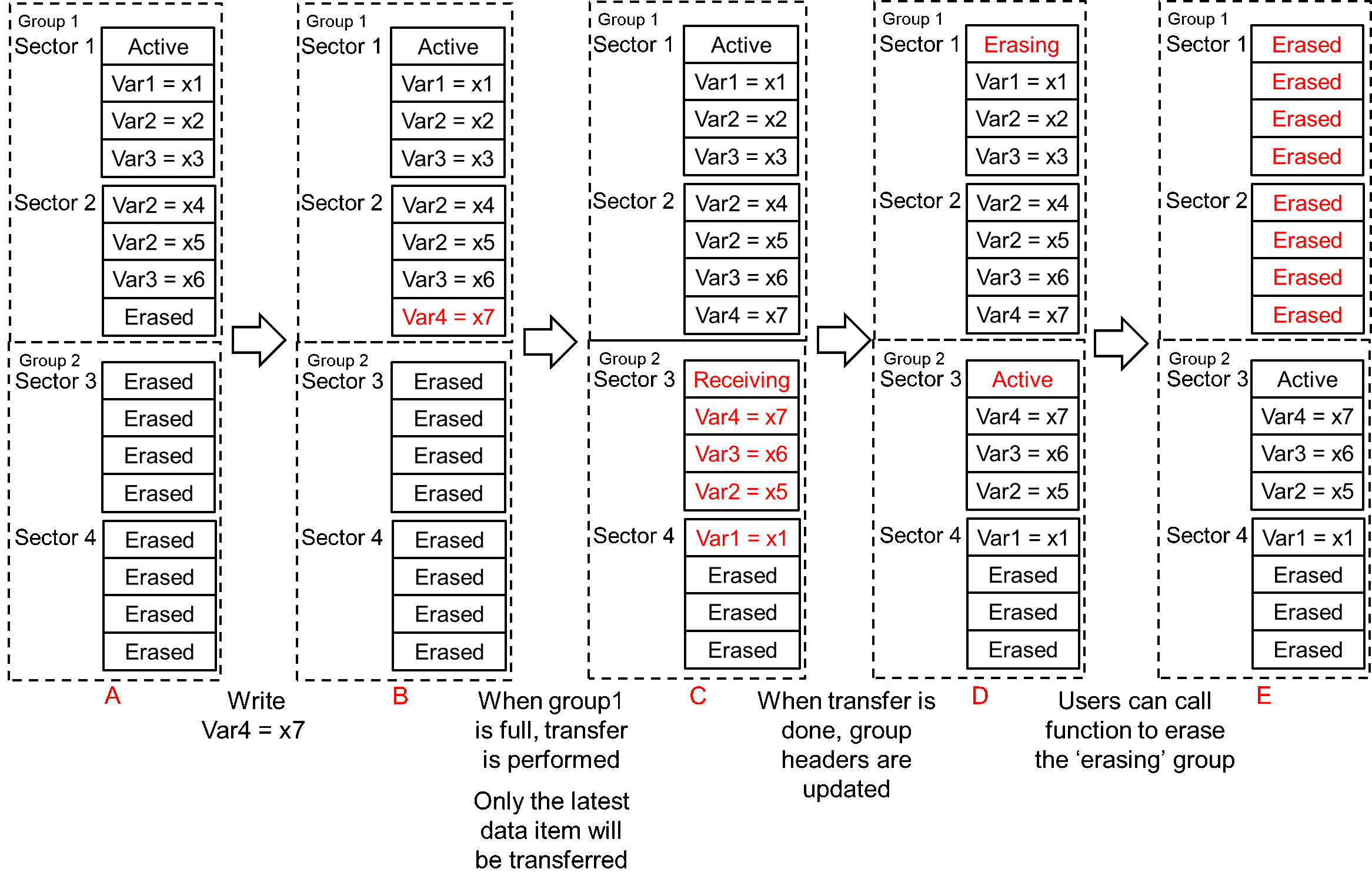
EmulationThe basic behaviors of EEPROM emulation can be seen in Figure 2-2. In A, although there are two Var3, meaning they have the same identifier, only the latter one is valid because it is newer. If var3 is read, x6 rather than x3 will be read. From A to B, write operation is performed and the group 1 is full, so the transfer operation will be performed. In C, Group 2 is marked as Receiving, and the latest data items are transferred to group 2. In D, after transfer group 2 is updated to Active. Group 1 is marked as ‘Erasing’ and waiting to be erased. The erase operation is performed only when the users call the function.
Users can choose the right time to erase according to the needs. It should be noted that not erasing in time will result in trying to write data into sectors with residual data. This may result in data corruption.
 Figure 2-2 The Basic Behaviors of EEPROM
Emulation