SLAAED1D June 2023 – October 2024 MSPM0C1103 , MSPM0C1103-Q1 , MSPM0C1104 , MSPM0C1104-Q1 , MSPM0G1107 , MSPM0G1505 , MSPM0G1506 , MSPM0G1507 , MSPM0G1519 , MSPM0G3105 , MSPM0G3105-Q1 , MSPM0G3106 , MSPM0G3106-Q1 , MSPM0G3107 , MSPM0G3107-Q1 , MSPM0G3505 , MSPM0G3505-Q1 , MSPM0G3506 , MSPM0G3506-Q1 , MSPM0G3507 , MSPM0G3507-Q1 , MSPM0G3519 , MSPM0L1105 , MSPM0L1106 , MSPM0L1227 , MSPM0L1228 , MSPM0L1228-Q1 , MSPM0L1303 , MSPM0L1304 , MSPM0L1304-Q1 , MSPM0L1305 , MSPM0L1305-Q1 , MSPM0L1306 , MSPM0L1306-Q1 , MSPM0L1343 , MSPM0L1344 , MSPM0L1345 , MSPM0L1346 , MSPM0L2227 , MSPM0L2228 , MSPM0L2228-Q1
- 1
- Abstract
- Trademarks
- 1Overview
- 2Step 1: MSPM0 Selection
- 3Step 2: MSPM0 Evaluation
- 4Step 3: Hardware Design
- 5Step 4: Mass Production
- 6Step 5: Quality and Reliability Instructions
- 7Common Questions
- 8Additional Information
- 9Summary
- Revision History
4.3 Schematic and PCB Generation
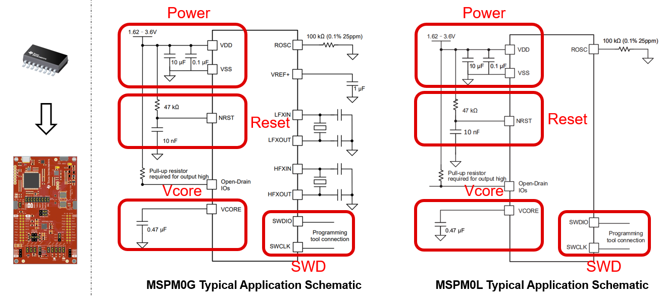
The minimum requirements (power, reset, and Vcore) with suggested values for MSPM0 hardware setup are shown in Figure 4-3.
- Power pin: TI recommends adding 10uF and 0.1uF capacitors, which are used to remove AC noise on the power rail.
- Reset pin: TI recommends adding a 47kR pullup resistor and a 10nF pulldown resistor. This makes sure that the MSPM0 releases from reset, after the power rail is stabilized. For some MSPM0 devices, the reset pin can be reused with another function, like I2C or UART. TI recommends reducing the resistor and capacitor, such as using a 2.2kR pullup resistor and 10pF pulldown capacitor.
- Vcore pin: This pin is used to stabilize the CPU voltage. For some MSPM0 devices, this pin is not included. If the pin is included, connect the pin to a 0.47uF capacitor.
 Figure 4-3 MSPM0 Minimum System
Other considerations when drawing a schematic file are listed in Figure 4-4.
- ROSC Pin: If users want to reach accurate high frequency clock with internal SYSOSC, then 0.1% resistor is suggested. Some low-cost devices cannot have this function.
- VREF+/VREF- Pin:
- If using an internal reference,then the G series require a 1uF capacitor between VREF+ and VREF- to support 4Msps ADC. For L or C series, the capacitor is not required, as the ADC speed is only support 200Ksps with internal Vref.
- If using an external reference, then all the MSPM0 devices require a 1uF capacitor between VREF+ and VREF-.
- Open-Drain IO: Open-Drain IO cannot output high voltage from the MCU side, so external pullup resistors are required, such as a 4.7kR capacitor.
- NRST: If reusing the reset pin as GPIO, then the pullup resistor and the pulldown capacitor are still required. This makes sure that the MCU is released from reset state after the power is stable.
- PA18: PA18 is the invoke pin to enter bootloader. Make sure this pin is not float or pullup. Otherwise, a user can change and disable the invoke pin in sysconfig, as shown in Section 7.3.
 Figure 4-4 MSPM0 Schematic
For further information about schematics or PCB design references, see the following links.
- MSPM0 L-Series MCUs Hardware Development Guide
- MSPM0 G-Series MCUs Hardware Development Guide
- Device-specific MSPM0 Launchpad EVM user's guide
- Device-specific MSPM0 data sheet