SLAAED1D June   2023  – October 2024 MSPM0C1103 , MSPM0C1103-Q1 , MSPM0C1104 , MSPM0C1104-Q1 , MSPM0G1107 , MSPM0G1505 , MSPM0G1506 , MSPM0G1507 , MSPM0G1519 , MSPM0G3105 , MSPM0G3105-Q1 , MSPM0G3106 , MSPM0G3106-Q1 , MSPM0G3107 , MSPM0G3107-Q1 , MSPM0G3505 , MSPM0G3505-Q1 , MSPM0G3506 , MSPM0G3506-Q1 , MSPM0G3507 , MSPM0G3507-Q1 , MSPM0G3519 , MSPM0L1105 , MSPM0L1106 , MSPM0L1117 , MSPM0L1227 , MSPM0L1228 , MSPM0L1228-Q1 , MSPM0L1303 , MSPM0L1304 , MSPM0L1304-Q1 , MSPM0L1305 , MSPM0L1305-Q1 , MSPM0L1306 , MSPM0L1306-Q1 , MSPM0L1343 , MSPM0L1344 , MSPM0L1345 , MSPM0L1346 , MSPM0L2227 , MSPM0L2228 , MSPM0L2228-Q1


  1.   1
  2.   Abstract
  3.   Trademarks
  4. 1Overview
  5. 2Step 1: MSPM0 Selection
  6. 3Step 2: MSPM0 Evaluation
    1. 3.1 Hardware Setup
      1. 3.1.1 Debugger Selection
      2. 3.1.2 LaunchPad Introduction
    2. 3.2 MSPM0-SDK Setup
      1. 3.2.1 MSPM0-SDK Installation
      2. 3.2.2 MSPM0-SDK Introduction
        1. 3.2.2.1 Documents Folder Introduction
        2. 3.2.2.2 Examples Folder Introduction
    3. 3.3 SysConfig Setup
      1. 3.3.1 SysConfig Installation
      2. 3.3.2 SysConfig Introduction
        1. 3.3.2.1 Basic Concept
        2. 3.3.2.2 Project Configuration View
        3. 3.3.2.3 Board View
        4. 3.3.2.4 NONMAIN View
        5. 3.3.2.5 SYSCTL View
        6. 3.3.2.6 Peripherals Setup
    4. 3.4 IDE Quick Start
      1. 3.4.1 CCS Quick Start
        1. 3.4.1.1 CCS Installation
        2. 3.4.1.2 Environment Setup
          1. 3.4.1.2.1 SDK Support Setup
          2. 3.4.1.2.2 SysConfig Support Setup
        3. 3.4.1.3 Import a SDK Example
        4. 3.4.1.4 Example Download and Debug
        5. 3.4.1.5 Migrating Between MSPM0 Derivatives
        6. 3.4.1.6 Generate Hex Files
        7. 3.4.1.7 Program NONMAIN
      2. 3.4.2 IAR Quick Start
        1. 3.4.2.1 Environment Setup
          1. 3.4.2.1.1 SDK Support Setup
          2. 3.4.2.1.2 SysConfig Support Setup
        2. 3.4.2.2 Import a SDK Example
        3. 3.4.2.3 Example Download and Debug
        4. 3.4.2.4 Migrating Between MSPM0 Derivatives
        5. 3.4.2.5 Generate Hex Files
        6. 3.4.2.6 Program NONMAIN
      3. 3.4.3 Keil Quick Start
        1. 3.4.3.1 Environment Setup
          1. 3.4.3.1.1 MSPM0 CMSIS-Pack Setup
          2. 3.4.3.1.2 Sysconfig Support Setup
        2. 3.4.3.2 Import a SDK Example
        3. 3.4.3.3 Example Download and Debug
        4. 3.4.3.4 Migrating Between MSPM0 Derivatives
        5. 3.4.3.5 Generate Hex Files
        6. 3.4.3.6 Program NONMAIN
  7. 4Step 3: Hardware Design
    1. 4.1 Obtaining a MSPM0 Package
    2. 4.2 Fix Pin Functions
    3. 4.3 Schematic and PCB Generation
  8. 5Step 4: Mass Production
    1. 5.1 Generate Production Image
    2. 5.2 Program Software
      1. 5.2.1 Uniflash Quick Start
        1. 5.2.1.1 Program Through SWD
        2. 5.2.1.2 Program Through Bootloader
        3. 5.2.1.3 Program Through CMD Line Interface
      2. 5.2.2 JFlash Quick Start
      3. 5.2.3 MSP-GANG GUI Quick Start
    3. 5.3 Program Hardware
  9. 6Step 5: Quality and Reliability Instructions
    1. 6.1 Quality and Reliability Material Entrance
    2. 6.2 Failure Information Collection and Analysis Guidance
  10. 7Common Questions
    1. 7.1 MSPM0 Program Failure
    2. 7.2 Unlock MCU
      1. 7.2.1 Unlock Through Factory Reset GUI Tool
      2. 7.2.2 Unlock Through Uniflash
      3. 7.2.3 Unlock Through CCS
    3. 7.3 MCU Performs Differently in Debug and Free Run
    4. 7.4 BSL Related Questions
    5. 7.5 Set SWD Password
    6. 7.6 CCS Common Questions
      1. 7.6.1 Setting Breakpoints at Wanted Places
      2. 7.6.2 Discovered Projects Become Gary
      3. 7.6.3 CCS Cannot Locate .h File
      4. 7.6.4 Install Arm GCC
      5. 7.6.5 Device is Not Connected After Entering Debug
      6. 7.6.6 Erase the Wanted Memory
      7. 7.6.7 Output Data Log From CCS
    7. 7.7 Keil Common Questions
      1. 7.7.1 Copy Keil Example Out of SDK
  11. 8Additional Information
    1. 8.1 Light an LED and CCS Quick Introduction
      1.      8.1.A Install CCS and SDK
      2.      8.1.B Hardware Setup
      3.      8.1.B Code Import
      4.      8.1.B Debug and CCS Quick Introduction
    2. 8.2 Steps to Generate the PCB Library
    3. 8.3 MSP-GANG Quick Introduction
  12. 9Summary
  13.   Revision History

Example Download and Debug

The default debugger selection is XDS110. To select J-Link, right click the Project->Properties and follow the steps to select J-Link.
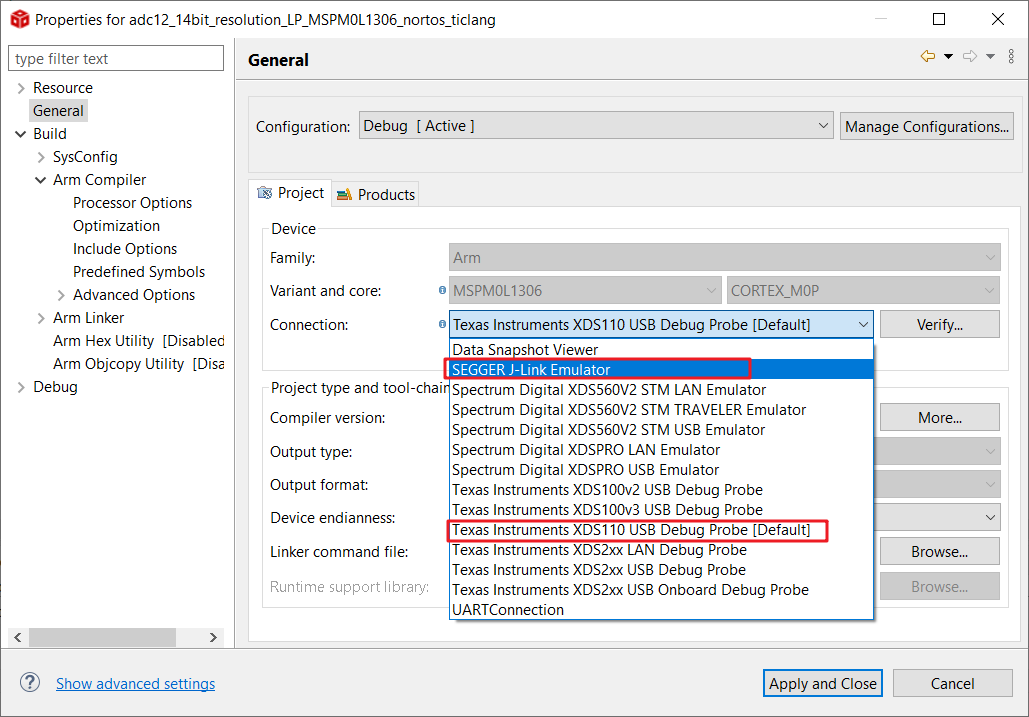
 Change Debugger SelectionFigure 3-24 Change Debugger Selection

Start debug by click the Build button at the top. After that, the window automatically moves from the CCS edit view to CCS debug view. After the MCU enters debug mode, click the Run button to enable the code running.

 Debug CodeFigure 3-25 Debug Code

This section is a quick introduction to CCS functions. The commonly used functions and meanings are shown in Figure 3-26.

 Commonly Used Debug FunctionsFigure 3-26 Commonly Used Debug Functions