SLUAAY2 December 2024 ISO5451 , ISO5451-Q1 , ISO5452 , ISO5452-Q1 , ISO5851 , ISO5851-Q1 , ISO5852S , ISO5852S-EP , ISO5852S-Q1 , UCC21710 , UCC21710-Q1 , UCC21717-Q1 , UCC21732 , UCC21732-Q1 , UCC21736-Q1 , UCC21737-Q1 , UCC21738-Q1 , UCC21739-Q1 , UCC21750 , UCC21750-Q1 , UCC21755-Q1 , UCC21756-Q1 , UCC21759-Q1
4.1 Short-Circuit Current-Based Protection Implementation
There are two implementation options for current detection approach:
- Shunt resistor based approach
- R-sense resistor based approach
Option1: Shunt resistor-based approach
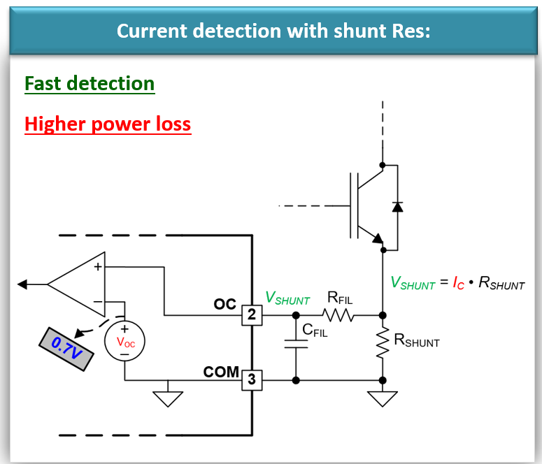
 Figure 4-2 Shunt Resistor Implementation
Circuit
Figure 4-2 Shunt Resistor Implementation
CircuitIn Figure 4-2, the current detection implementation approach is shown with an Rshunt resistor. The Rshunt is added in the high current path, the voltage across the resistor is measured using the RC filter by the OC detection pin. When the voltage across the resistor is higher than the OC detection threshold, the gate driver triggers a fault event and turns off the gate driver output to protect the system.
This implementation approach is very simple and fast. However, as the resistor is in the high current path, this method causes high-power loss. Due to that, this approach is not recommended for systems with high operating current, to minimize the power loss.
Option2: Rsense resistor-based approach:
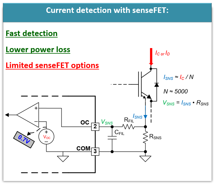
 Figure 4-3 Rsense Resistor
Implementation Circuit
Figure 4-3 Rsense Resistor
Implementation CircuitThis approach is similar to the Rshunt-based approach. However, in the case of the Rsense-based approach, the sense resistor is added in the sense path, not on the high current path. Some power modules have a separate terminal that has around 5000x lower current sense path apart from the high current path. The sense resistor is added in the lower current sense path and hence the power loss is minimal. This approach is faster and has lower power loss as well. However, it can be implemented only with the power modules with the sense option.