SLUAAY2 December 2024 ISO5451 , ISO5451-Q1 , ISO5452 , ISO5452-Q1 , ISO5851 , ISO5851-Q1 , ISO5852S , ISO5852S-EP , ISO5852S-Q1 , UCC21710 , UCC21710-Q1 , UCC21717-Q1 , UCC21732 , UCC21732-Q1 , UCC21736-Q1 , UCC21737-Q1 , UCC21738-Q1 , UCC21739-Q1 , UCC21750 , UCC21750-Q1 , UCC21755-Q1 , UCC21756-Q1 , UCC21759-Q1
2 SiC and IGBT Characteristics
Though both used in high-voltage, high-power systems, IGBT and SiC FETs are intrinsically different in their voltage-current characteristics, resulting in difference in their overvoltage and short-circuit protection timing and shutdown energy.
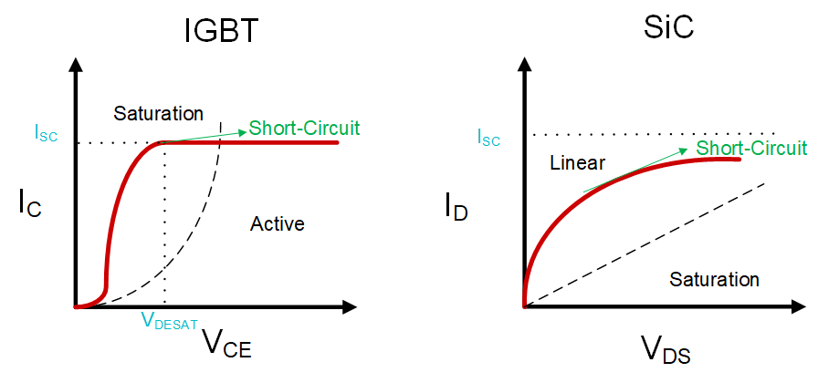
Both Si IGBT's and SiC FET's regions of operation are shown in Figure 2-1. For IGBTs, at low collector-emitter voltage (VCE), the device is in its linear region, and the collector current (IC) increases as VCE increases. IGBT has a saturation VCE voltage, and beyond the VCE saturation point, it operates in the active region, meaning the current is relatively flat as VCE increases. This saturation VCE voltage is usually used to determine when the short-circuit protection starts to engage, with the corresponding IC being the short circuit threshold current (ISC). Since only VCE increases and Ic stays stable during IGBT short circuit, the power dissipation increases relatively slowly, so IGBTs usually can tolerate longer duration of short-circuit event (around 10μs).
SiC, on the other hand, usually operates in the linear region. As a short-circuit event happens, the drain-source voltage (VDS) and the drain current (ID) increase simultaneously, resulting in faster-rising power dissipation. Because of this operating mode, the timing is more critical. SiC can usually only tolerate a short duration of short-circuit event (typically 2-3μs) before the power switch starts breaking down.
Thus, it is crucial to select the right short-circuit protection mechanism as well as suitable protection voltage (VCE/VDS) and load current (IC/ID) threshold to safely and efficiently turn off the device when a short-circuit event happens.
 Figure 2-1 SiC and IGBT
Characteristics