SLVAE51A November 2018 – October 2020 LM7310 , TPS2100 , TPS2101 , TPS2102 , TPS2103 , TPS2104 , TPS2105 , TPS2110 , TPS2111 , TPS2111A , TPS2112 , TPS2112A , TPS2113 , TPS2113A , TPS2114 , TPS2114A , TPS2115 , TPS2115A , TPS2120 , TPS2121 , TPS25947
3.1 Discrete
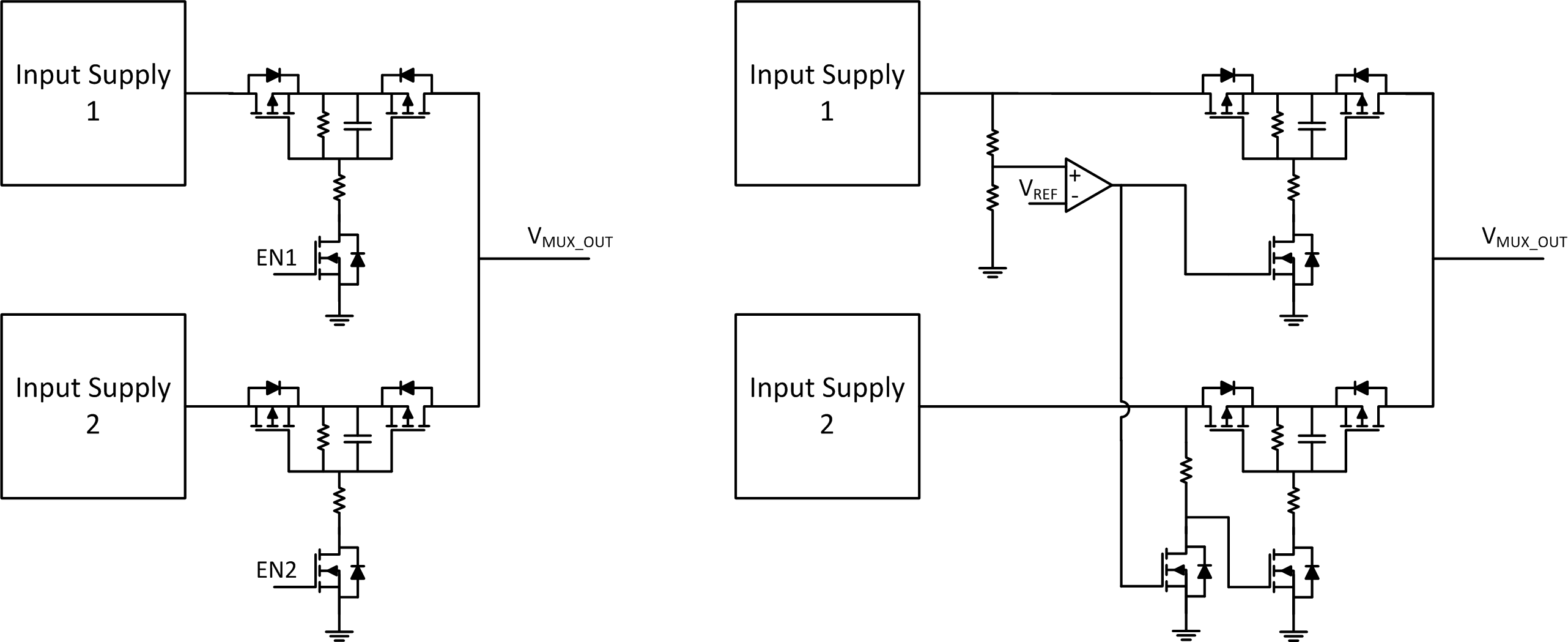
A 2-input priority Power MUX solution can be implemented using 4x discrete MOSFETs (2x paths of back-back FETs) along with manual or automatic logic to determine which path to enable. PMOS based solutions are commonly used when there is no higher voltage source or charge pump available (otherwise an NMOS-based architecture would be advantageous).
 Figure 3-1 Manual and Automatic Discrete Power MUX with Priority
In this example, the manual power MUX can be controlled with two EN pins tied to a microcontroller. The microcontroller would need logic to ensure only one set of switches is on at a time, to prevent reverse current flow. The automatic MUX features a comparator followed by inverter logic to ensure only one set of switches is turned on at a time. The comparator is configured to turn on the top set of switches when input 1 is present, otherwise default to input 2 when present.