SLVAFX0 October 2024 TLV702 , TLV703 , TLV755P , TPS74401 , TPS7A13 , TPS7A14 , TPS7A20 , TPS7A21 , TPS7A49 , TPS7A52 , TPS7A53 , TPS7A53B , TPS7A54 , TPS7A57 , TPS7A74 , TPS7A83A , TPS7A84A , TPS7A85A , TPS7A91 , TPS7A92 , TPS7A94 , TPS7A96 , TPS7H1111-SP
- 1
- Abstract
- Trademarks
- 1Introduction to linear regulator turn-on time
-
2What impacts the LDO rise time?
- 2.1
Simple Use Cases
- 2.1.1 Case 1: LDO with an NR filter but without CFF capacitance
- 2.1.2 Case 2: NR filter with a CFF capacitance
- 2.1.3 Fast-charge circuitry
- 2.1.4
Non-ideal LDO behavior
- 2.1.4.1 Applied voltage bias
- 2.1.4.2 Fast charge current tolerance
- 2.1.4.3 Internal error amplifier offset voltage
- 2.1.4.4 Temperature impacts the fast-charge current source
- 2.1.4.5 Error amplifier common mode voltage
- 2.1.4.6 Reference voltage (VREF) ramp time dominates the turn-on time
- 2.1.4.7 Start-up during dropout mode
- 2.1.4.8 Large values of COUT induce internal current limit
- 2.1.4.9 Limitations of large-signal LDO bandwidth
- 2.2 Specific Use Cases and Examples
- 2.1
Simple Use Cases
- 3System Considerations
- 4LDO regulators referenced in this paper
- 5Conclusion
- 6References
2.2.2 Case 4: Precision voltage reference with IFC fast charge and no RNR/SS
If Figure 2-1 describes the LDO architecture and the fast charge circuit uses only IFC (that is, RNR/SS disconnects temporarily) then Equation 5 can be rewritten as Equation 17 when t < tCO. Equation 11 through Equation 15 and Equation 17 through Equation 20 are used to calculate the turn-on time for these LDO regulators.
When t ≤ tCO, use Equation 17 and Equation 18 to calculate VFB(t) and VTOP(t).
When t > tCO, use Equation 13, Equation 15, Equation 19 and Equation 20 to calculate VFB(t) and VTOP(t).
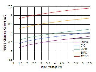
The TPS7A84A uses a precision voltage reference, low pass NR filter, external CFF capacitor across RTOP, and includes a constant current fast charge circuit. Figure 2-16 from the TPS7A84A data sheet describes the fast charge current versus input voltage and temperature. VCO is 97% of VREF. The CNR/SS capacitor is rated for 50V and the effective capacitance is nearly constant at 9.6nF. The EVM was used for the measurements.

| from TPS7A84A data sheet | VBIAS = 0V |

| TPS7A84A EVM | VOUT = 2.4V |