SNVAA93 December 2023 LM65645-Q1 , LM70660 , LM706A0 , LM706A0-Q1 , LM70840 , LM70840-Q1 , LM70860 , LM70860-Q1 , LM70880 , LM70880-Q1 , LMR38020-Q1 , LMR38025-Q1
3.1 Bead Consideration
It is evident that the addition of a single-stage EMI filter in front of the converter is effective in reducing DM noise at the switching frequency and its harmonics. However, in some cases, a two-stage filter may be necessary to achieve greater attenuation of DM noise. To maintain a low cost and high-power density solution, an input choke is not utilized in this design.
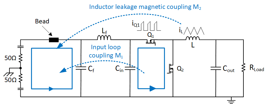
Furthermore, Figure 3-25 illustrates the inclusion of a bead with a higher self-resonant frequency (SRF) in front of the EMI filter. This serves to increase the input impedance at high frequencies, thus suppressing DM noise caused by input current spikes and magnetic coupling.
 Figure 3-2 Effect of Bead Adding in Front of EMI Filter
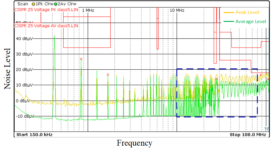
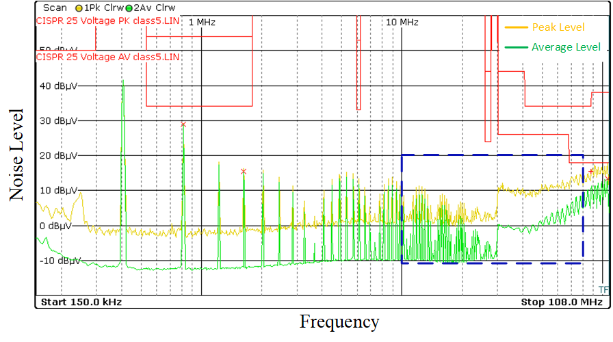
Figure 3-22 and Figure 3-12 present the EMI test results with and without the ferrite bead. The data indicates that the inclusion of the bead leads to noticeable reduction in noise levels particularly in the 10 MHz-70 MHz range where the peak noise is approximately 8db lower with the bead and the average noise is reduced by 10db. These results demonstrate the effectiveness of the bead in mitigating noise in the high frequency range.
 Figure 3-3 Conducted EMI Test Result Without Ferrite Bead
 Figure 3-4 Conducted EMI Test Result With Ferrite Bead