-
Simulate Inductive Sensors Using FEMM (Finite Element Method Magnetics) SNOAA04A March 2020 – June 2021 FDC1004 , FDC1004-Q1 , FDC2112 , FDC2112-Q1 , FDC2114 , FDC2114-Q1 , FDC2212 , FDC2212-Q1 , FDC2214 , FDC2214-Q1 , LDC0851 , LDC1041 , LDC1051 , LDC1101 , LDC1312 , LDC1312-Q1 , LDC1314 , LDC1314-Q1 , LDC1612 , LDC1612-Q1 , LDC1614 , LDC1614-Q1 , LDC2112 , LDC2114 , LDC3114 , LDC3114-Q1
-
Simulate Inductive Sensors Using FEMM (Finite Element Method Magnetics)
Simulate Inductive Sensors Using FEMM (Finite Element Method Magnetics)
Trademarks
All trademarks are the property of their respective owners.
1 Introduction
Simulation tools similar to SPICE are an important part of the design process for many systems because they reveal design problems before prototypes are built. SPICE, however, is not suitable to simulate inductive sensing systems because it does not include target interactions with the sensor coil. The open-source magnetics simulation software FEMM (Finite Element Method Magnetics) can provide information about these target interactions and the robustness of the system before production. Before using FEMM, we recommend using the LDC Tools Excel calculator to design the sensor coil, as well as reading LDC Sensor Design and LDC Target Design. For smooth targets that are at least as large as the sensor coil, TI also recommends using the Excel_FEMM tool (included in LDC Tools), which will automatically simulate custom sensors in FEMM. For smaller or irregularly shaped targets, the following guide will give the reader working knowledge of FEMM for inductive sensing simulations. The program can be downloaded from the FEMM home page.
2 Inductive Sensor Simulation
- Design a coil using the LDC Tools Excel calculator's Spiral Inductor Designer. The dimensions of this coil will be used to create the FEMM simulation. Instructions are embedded in the tool.
- Create a new problem
- Open FEMM
- Click File → New
- In the Create a new problem dialog box, select Magnetics Problem and click OK.
 Figure 2-1 Create a New Problem Dialog Box
 - Make the new problem a planar problem or an axisymmetric problem.
When choosing between the two problem types, consider the geometry of the coil. For both planar and axisymmetric problems, the FEMM workspace forms a cross section of the coil and target. The workspace is a slice of the PCB coil such that all layers and traces of the PCB are visible. Keep this in mind while constructing the coil. It is important to construct the cross section such that the simulation will create a coil shape. See how each problem type turns the 2D workspace into a 3D solution:
- Planar problems:
Planar problems expand along the axis perpendicular to the plane. The user must specify the distance of this expansion. This type of problem is most often used to simulate racetrack coils. However, planar problems cut off the rounded edges of the coils, leaving only the long parallel section. This makes the simulation much less accurate than spiral coil simulations using axisymmetric problems.
 Figure 2-2 Example Planar Problem Workspace With Labeled Traces and Target
 - Axisymmetric problems:
Axisymmetric problems rotate around a user-specified axis. This type of problem is the most useful for inductive sensing simulations and should be used for all circular coils. Note that coils simulated with this problem type will not be true coils, but will be a series of concentric circles. Even so, the coils are fairly accurate simulations.
 Figure 2-3 Example Axisymmetric Problem Workspace With Labeled Traces and Target
- Planar problems:
- Define the problem.
- Navigate to the Problem menu shown in Figure 2-4.
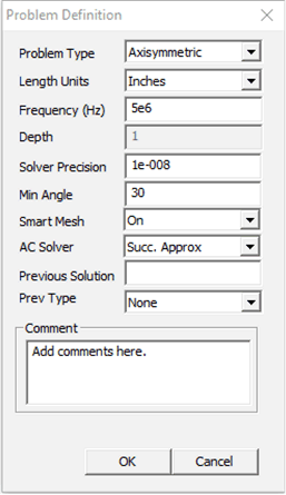
- In the Problem Definition dialog box, choose planar or axisymmetric for the Problem Type. If “planar” is selected, enter the depth of the problem expansion in the Depth field.
- Enter the appropriate length units for the coil design in the Length Units field. Typically mm or mils are most useful.
- Define a Frequency (Hz). All magnetic problems must have a defined frequency. For inductive sensing problems, this is comparable to choosing a capacitor for a known inductor.
Use the Spiral Inductor Designer in LDC Tools to calculate a frequency and enter that frequency in the problem Frequency (Hz) field. If the FEMM simulation includes a target, use the sensor frequency with target interaction.
- In the AC Solver field, select Succ. Approx. Ignore the other fields and click OK.
 Figure 2-4 Problem Definition Dialogue Box
 - Place nodes
- Use this button
 to place nodes. Use either segments
  or arcs
  to connect them. At least two nodes must be placed before placing segments. These will form the boundaries of your shape(s).
 Use the trace width, trace spacing, and trace thickness from the Spiral Inductor Designer to create a cross section of each trace. Here are key tips for placing objects:
- It can be challenging to place nodes exactly in-line with each other. It may be easier to place one node, copy it, and specify X- and Y- translations for the new nodes. Note that the units are specified in the Problem Definition menu.
- Click close to the desired nodes to place segments or arcs on the node.
- Though the coils in this tutorial will use rectangular traces, the best approximation of real traces is a trapezoidal shape.
- Other helpful tips when moving objects:
- Right-click near an object to select it.
- Double-right-click the object to show the X,Y position of the object.
- Navigate with keyboard arrows.
- Click the Page Up and Page Down keys to zoom in and out.
- Undo only works ONCE.
- Click the
 button to move objects.
 - Click the
 button to copy objects.
 - Click the
 button to select a group of
objects. Then click the
  button to highlight objects in a
rectangular area or the
  button to highlight objects in a
circular area. Press the space bar to join the objects into a
group.
 - Click the
 button to scale
- For axisymmetric problems only: Mouse over the leftmost segment or arc or double-right-click the arc and look at the bottom left corner of the screen to determine the X,Y location of the object. Select all drawn objects and translate them left so that the leftmost segment or arc now has an x-value equal to the inner radius of the sensor coil. The axis of rotation will be the y-axis, so offsets in the x-direction will form gaps or holes in the object.
- Use this button
- Define boundaries
- Click the
 button to open the Boundary Builder.
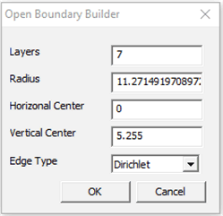
 - The Boundary Builder builds the model, shows the axis of symmetry, and defines several boundaries that form a gradient to infinity.
- Leave the values in the Open Boundary Builder dialog box unchanged and click OK.
 Figure 2-5 Boundary Builder Dialogue Box
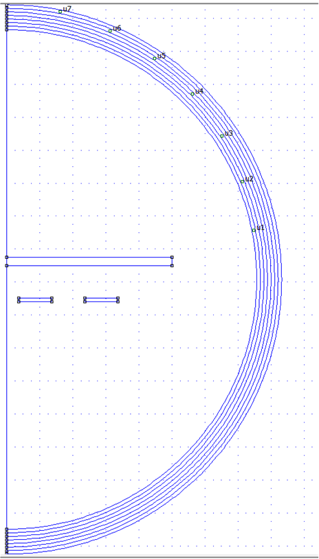
 - The workspace should now look similar to Figure 2-6 for axisymmetric problems or similar to Figure 2-7 for planar problems:
 Figure 2-6 Axisymmetric
Problem With Boundaries
 Figure 2-7 Planar Problem
With Boundaries
- Click the
- Define materials
- Select the circular green button
 to place block labels. Place a block label
inside each boundary area, including the white space inside the outer
boundary. The result should look something like Figure 2-8:
  Figure 2-8 Axisymmetric
Problem Workspace With Block Labels
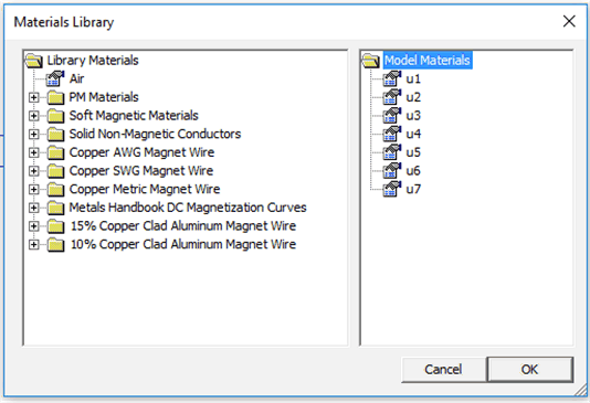
 - Each block label must be changed from <None> to a defined material. First, the materials must be added to the Materials Library. Navigate to Properties → Materials Library.
 Figure 2-9 Default Materials Library
 - Typically, the engineer only uses air, copper, and the target material if the material is not copper. Drag Air from the left side to the right side of the menu. Open the Solid Non-Magnetic Conductors folder and drag Copper to the right side of the menu. Click OK.
 Figure 2-10 Materials Library With Air and Copper Added to Model Materials
 - The copper coil requires a special material type. Navigate to Properties → Materials. In the Property Definition menu, click Add Property to open the Block Property dialog box.
 Figure 2-11 Block Properties Menu
 - In the Name field, enter the material name Copper Coil.
- In the B-H Curve drop-down menu, select Linear B-H Relationship.
- The Linear Material Properties do not need to be modified. Copper is a conductor, therefore the material will have a relative permeability of 1.
- Change the Electrical Conductivity field to 58.5 MS/m.
- Change the Special Attributes: Lamination & Wire Type to Magnet wire.
- In the Strand dia, mm field, enter the
strand diameter based on the trace width and copper thickness of
the real coil. Use Equation 1 to calculate the equivalent strand diameter:
- The trace height and width form the cross section of the trace. The area of the equivalent copper wire must equal the cross sectional area of the PCB trace.
- Solve for r in mm. Use 2r for the strand diameter and enter this value in the Strand dia, mm field.
- This calculated diameter does not affect the size of the inductor nor the spacing. This is determined by the boundaries in the workspace. The strand diameter does affect the coil's series resistance.
Equation 1.- T is the trace thickness in mm
- W is the trace width in mm
- r is the strand radius in mm
- Right-click near the material labels to highlight
the names. Press the space bar to open the Properties for selected
block menu. Change the Block type to the appropriate material
for the area. Repeat this for all material labels.
 Figure 2-12 Properties for
Selected Block Menu
 - After these steps, the workspace should look
something like Figure 2-13:
 Figure 2-13 Axisymmetric
Problem Workspace With Defined Materials
- Select the circular green button
- Add circuits to the problem
- Navigate to the Properties → Circuits menu. In the Property Definition dialog dox, click Add Property.
- In the Circuit Property dialog box, name the circuit and specify an operating current.
- The current value is not especially important. A value anywhere from 1 mA to 1 A is acceptable.
- Make sure the Series option is checked and click OK.
 Figure 2-14 Circuit Property Menu
 - For planar problems only:
- For racetrack coils and similar circuits, the parallel traces are not automatically connected by the planar expansion. At least two separate circuits are required to correctly model the current flow.
- To model the current flow, define two circuits with
the same current magnitude. One should be positive and the other
should be negative. Assign one to each side of the racetrack
coil. Your workspace should look similar to Figure 2-15:
 Figure 2-15 Example Planar Problem Workspace With Defined Circuits
for Racetrack Coil
- Right-click the material nodes again and click the space bar to return to the Properties for selected block menu.
 Figure 2-16 Properties for Selected Block Menu
 - Select the circuit that you just created in the In Circuit field.
- Specify the number of turns in the coil. This will not change the size of the coil and only change the generated magnetic field. The simulation will yield the most realistic results if only one turn is used per coil boundary and the number of coil boundaries is equal to the number of turns in the real coil.
- Leave the Let Triangle choose Mesh Size box selected.
- Repeat this process for all boundaries in the coil.
The workspace should now look similar to Figure 2-17:
 Figure 2-17 Axisymmetric
Problem Workspace With Defined Circuits
- Generate the answer file
- Click the Solve button
 to generate the answer file.
 - Answer files will be saved in the .ans file format in the current working directory.
- Click the Solve button
3 Using the Electromagnetic Problem Answer File
- Open the .ans file
- The .ans file will generate in the same directory as the .FEM file. Open the .ans file.
- Note that if any changes are made to the .FEM file, solving the problem again will overwrite the .ans file.
- The .ans file should show
the magnetic field lines, which should bend around the target. The outer
boundaries represent a gradient to infinity, so the magnetic field lines
may contort in this region. Only the region contained by the innermost
boundary line is of interest.
 Figure 3-1 Axisymmetric
Answer File Showing the Contour Plot of the Magnetic Field
Around the Coil and the Target
- Change the contour plot options
- Navigate to View →
Contour Plot, or click on the Contour Plot button

- In the Contour Plot
Options, change the number of contour lines, as well as their
upper and lower bounds, and click OK.
 Figure 3-2 Contour Plot
Options Menu
- Navigate to View →
Contour Plot, or click on the Contour Plot button
- Add various density plots
- Navigate to View →
Density Plot, or click on the Density Plot button

- In the Dialog menu, check the Show Density Plot box.
- Select the desired
Plotted Value, generally |Flux Density| (T) or |Current
Density| (MA/m2). Flux density is useful for determining
optimal target placement, because we want the target in the area of
highest flux density. Current density is useful for displaying eddy
currents.
 Figure 3-3 Axisymmetric
Answer File Showing Flux Density Plot
 Figure 3-4 Axisymmetric
Answer File Showing Current Density Plot That Shows Eddy
Currents on the Target
- Navigate to View →
Density Plot, or click on the Density Plot button
- Change the mesh
The mesh is one of the most important aspects in generating an accurate answer file. Generally, it is best to choose a small mesh around the coils, the target, and the axis of symmetry (for axisymmetric problems).- To display the mesh,
navigate to View → Show Mesh, or click the Show Mesh
button

- To change the mesh, return to the .FEM file.
- To select the desired
material, click the green materials button
 then right-click near the desired material
node and press the space bar. The Properties for selected block
menu should open.
 - Uncheck the Let Triangle choose Mesh Size box.
- Enter a new Mesh size. A mesh size around 0.01 is a good starting point. Note that the problem must be solved again to reflect any changes.
- To display the mesh,
navigate to View → Show Mesh, or click the Show Mesh
button
- View the inductance of the coil
- Click the Inductor
button
 at the top.
 - The Circuit
Properties menu should open. The inductance will be listed as
Flux/Current.
 Figure 3-5 Circuit
Properties Menu
- Click the Inductor
button
4 Calculating Resolution
Most LDC devices measure shifts in inductance by measuring the resonant frequency of an LC tank circuit. For this reason, it is most useful to calculate LDC resolution in units of Hz. However, many users will spec their desired resolution in terms of the distance between a target and the sensor coil, and also want to determine the SNR of the frequency shift associated with a target movement. For these reasons, this section will give a set of steps to use FEMM to simulate the sensor inductance, and use the LDC EVM and software GUI to estimate the SNR.
- Calculate the Frequency:
- A real inductive sensor will consist of the sensor
coil and fixed, physical capacitor. FEMM accurately calculates the
magnetic fields of the coil - and therefore its inductance - but it will
not include the effects of the capacitor.
To work with this limitation, we describe two sets of steps below. The first will assume the sensor coil geometry and the capacitor value are known, but the coil inductance and tank circuit resonant frequency are unknown. The second set of steps will be be based on a known coil geometry and tank circuit resonant frequency, but the coil inductance and the capacitance are unknown. This will allow you to simulate the coil in FEMM to determine its inductance, and then calculate the capacitance.
Neither approach considers the effect of the capacitor into the FEMM simulations. Instead, a few calculate/simulate steps will be used to to quickly iterate to the final inductance value and resonant frequency.
(1) - Known Coil Geometry and Capacitor Value
-
For the first iteration, pick a frequency and a maximum target distance and complete Part 1. Use the FEMM .ans file to calculate the inductance.
- Use the known
capacitance and the newly calculated inductance to calculate the
corresponding resonant frequency as shown in Equation 2: Equation 2.
- Use the new frequency and the original target distance in FEMM to calculate a new inductance.
- Repeat steps ii and iii until the inductance does not change significantly between iterations.
- Move the target by the minimum distance for the desired resolution and repeat steps i-iv. Determine the difference in calculated frequencies between the two target positions.
(2) - Known Coil Geometry and Tank Circuit Resonant Frequency
-
- Complete Part 1 using the
resonant frequency and target distance. Use the FEMM .ans file to
calculate the inductance.
- Calculate the
capacitance using:Equation 3.
- Move the target by the minimum distance for the desired resolution and perform the steps i - iv in (1) just above. Determine the difference in calculated frequencies between the two target positions.
- Calculate the
capacitance using:
- A real inductive sensor will consist of the sensor
coil and fixed, physical capacitor. FEMM accurately calculates the
magnetic fields of the coil - and therefore its inductance - but it will
not include the effects of the capacitor.
- Calculate Resolution Using Simulation Results and
Noise Floor Measurements:
- Measure the Noise Floor: For inductive sensing applications, the first step is to measure the noise floor for the system. Basic noise floor measurements can be done using the LDC evaluation modules, which can be purchased on ti.com. Accuracy can be improved - with respect to the end application - by making measurements over the expected temperature range, and using a sensor designed for the end application. The default evaluation module, however, will still provide a reasonable noise floor estimate.
To measure the noise floor using an evaluation module, first download and open the Sensing Solutions GUI. For more detailed installation and use instructions, see the user’s guide associated with the EVM.
- Open the GUI and navigate to the Configuration tab.
- Configure the RCOUNT setting so that the LDC device
will sample the sensor frequency at the desired rate.
- For non-default sensors, the user must use an oscilloscope now to verify that the sensor oscillation amplitude and the sensor frequency are within the acceptable range for the specific device, as specified in the datasheet.
- If the sensor oscillation amplitude is outside of the recommended range, the sensor drive current will need to be modified. Please see Setting LDC1312/4, LDC1612/4, and LDC1101 Sensor Drive Configuration for instructions.
- If the sensor oscillation frequency is outside of the frequency range supported by the device, either the inductor or the capacitor in the LC tank will need to be modified.
- Next, navigate to the Data Streaming tab.
- Click the Start Streaming button to begin the noise floor measurement.
- Ensure that the graph displays Detected Sensor Frequency (MHz), which is controlled by the drop-down menu in the upper left corner.
- Click on the Show Statistics button to display the average and standard deviation. The data's standard deviation will be used to estimate the system noise. Increase the number of decimals of the standard deviation until the last digit is rapidly changing.
- Calculate the Final
Resolution via Signal-to-Noise Ratio (SNR):
To calculate the SNR, use Equation 4, using three times the measured standard deviation as the total noise.- Remember that the SNR should be at least 10 to achieve the desired resolution in a real-world application.
- Note that resolution significantly increases when the target is closer to the sensor. The FEMM simulations should test the resolution at both the minimum and maximum target distances using one of the two steps in (1) just above.
- Also note that very fine resolutions may not be achievable at high sample rates. For more information about how sample rate affects resolution, see the Optimizing L Measurement Resolution for the LDC161x and LDC1101 application report.
- If the FEMM simulations show that the desired resolution is not viable, then the sensor design or the target design must be modified. LDC Sensor Design and LDC Target Design are good resources.
Equation 4.