SBAA201A March 2013 – March 2023 ADS1120 , ADS1120-Q1 , ADS1147 , ADS1148 , ADS114S06 , ADS114S06B , ADS114S08 , ADS114S08B , ADS1220 , ADS122C04 , ADS1247 , ADS1248 , ADS124S06 , ADS124S08
3.1 Noise Performance Using Mismatched RC Filters
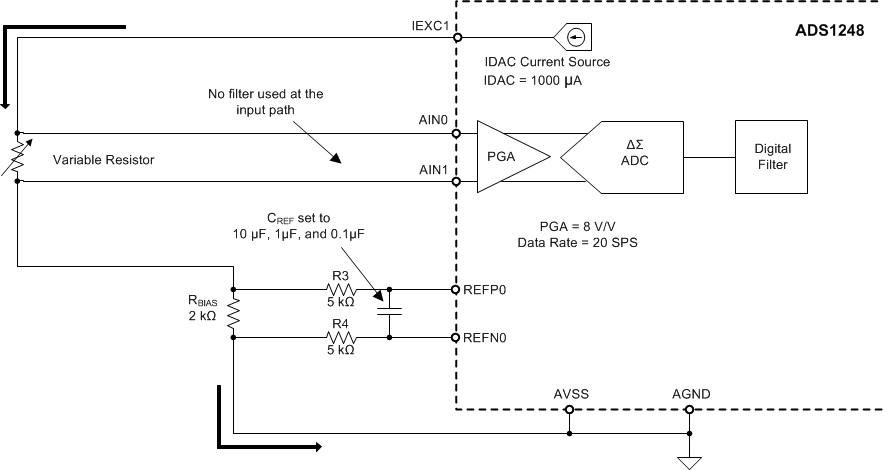
To illustrate increasing noise when using unmatched filters in the ratiometric circuit, ADS1248 noise-measurement tests are performed using mismatched input and reference filters. In this experiment, the measurements are performed applying a low-pass filter in the reference path while no filter is used at the inputs of the PGA. Different CREF_DIFF capacitors are used to implement a low-pass filter at the reference with corner frequencies of 130 Hz, 13 Hz, and 1.3 Hz, respectively.
The ADS1248 IDAC current is set to 1000 µA, producing a voltage reference of 2 V across the 2-kΩ RBIAS resistor. The ADS1248 is configured at a data rate of 20 SPS with PGA gain of 8 V/V, allowing a full-scale voltage of 250 mV. The RTD sensor in this case was simulated using a resistance decade box. The resistance at the input was swept from 0 Ω to 250 Ω in order to produce an input voltage of 0 mV to 250 mV.
 Figure 3-1 Circuit for Noise Measurement Experiment with Mismatched RC Filters
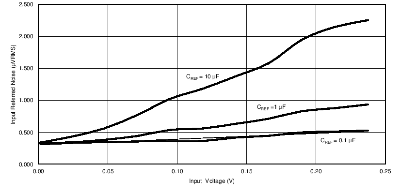
Figure 3-2 shows experimental noise measurements using the ADS1248 with the different reference input filters, but no signal input filter. The noise measurements show a pattern, where the conversion noise in the measurement increases as the input differential voltage increases. There is no filter in the ADC input path; therefore, the noise produced by the excitation source is reflected at the ADC inputs. However, the RC filter at the reference path attenuates noise components seen at the reference inputs. The noise signals seen by the reference inputs and the ADC are not attenuated equally; therefore, ratiometric noise cancellation is not effective.
 Figure 3-2 Input Referred Noise vs Input Voltage Using Mismatched RC Filters
The input referred noise of the ADS1248 is approximately 350 nVrms when the device is configured with a PGA gain of 8 V/V at 20 SPS. In the case where CREF = 10 µF, where a 1.3-Hz heavy low-pass filter is present in the reference path, the increased noise due to the mismatched RC filters is the most severe. The input referred noise changes from 350 nVrms to 1 µVrms as the differential input voltage approaches the full-scale range.
When the reference input time constant is smaller (CREF = 0.1 µF), the increasing noise versus input level is not as severe.
The ADC output conversion results are proportional to VIN / VREF. As the input signal increases, uncorrelated noise present on either VIN or VREF results in increased measurement noise. When the filters are matched, the noise is correlated and the measurement noise remains constant. This configuration is described next.