SCEU026 February 2024 SN74AVC8T245 , SN74AVC8T245-Q1 , SN74AXC8T245 , SN74AXC8T245-Q1 , SN74LVC8T245 , SN74LVC8T245-Q1 , SN74LXC8T245 , SN74LXC8T245-Q1 , TXV0106 , TXV0106-Q1 , TXV0108 , TXV0108-Q1
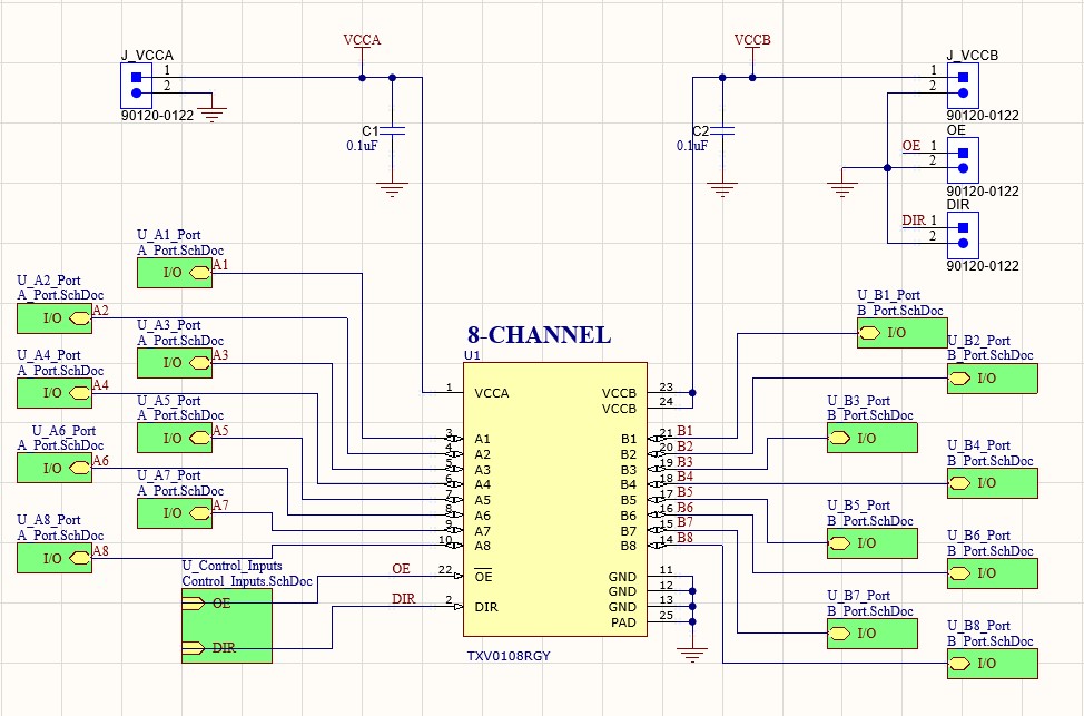
3.1 Schematic
TXV0106-EVM Schematic illustrates the EVM schematics. Increase the zoom level for clarity.
 Figure 3-1 TXV0106-EVM Schematic
 Figure 3-2 TXV0108-EVM Schematic
 Figure 3-3 TXV0108-EVM A-Ports
 Figure 3-4 TXV0108-EVM B-Ports
 Figure 3-5 TXV0108-EVM Control
Inputs
 Figure 3-6 TXV0108-EVM Control Inputs (as
populated)