SLAA901 July 2020 – MONTH TAS2555 , TAS2557 , TAS2559 , TAS2560 , TAS2562 , TAS2563 , TAS2564 , TAS2764 , TAS2770 , TAS2780 , TAS2781
3.2 Capacitance Only Filter Impact on Efficiency
The output filter will also introduce efficiency loss. When a square pulse is driven into to a capacitive path to ground, there will be a spike in leakage current during voltage transitions. The expected peak current can be calculated using the derivative form of the capacitor equation:
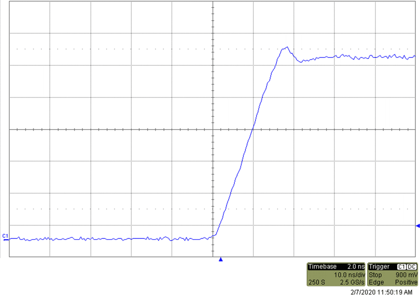
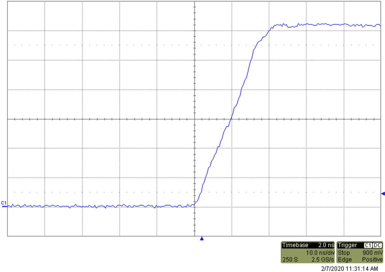
During high dV/dt events, such as the rising or falling edge of a pulse we will observe significant current through the capacitor. Typical dV/dt rates for several common devices are shown in the following images.
 Figure 3-2 TAS2770: dV/dt = 2 V/ns
 Figure 3-3 TAS2562: dV/dt = 0.7 V/ns
 Figure 3-4 TAS2563: dV/dt = 0.7 V/ns
 Figure 3-5 TAS2564: dV/dt = 0.7 V/ns
For example, if we were to use a total capacitance of 250 pF on the 2V/ns output of TAS2770 we could expect to see a peak current into the capacitor of about 0.5 A.
If not selected carefully, a capacitor directly on the output will cause peak currents that exceed the over current protection of the amplifier. The maximum capacitor value will be directly related to the maximum of the current spike observed during the rise and fall of the output switching. This must always be selected to keep below the over current threshold of the amplifier. It is never recommended to design a capacitor only filter. If one is used, the maximum theoretical value should always be avoided. Process variations in ceramic capacitors are typically in the range of 10-20%. Designing near the maximum will typically result in a production unit that enters over current protection when driving power at levels within the typical maximum output power range. This practice also results with the greatest efficiency losses in the filter. After considering both of these concerns, it is always recommended to start the filter design with an inductiver or ferrite element first, and then add a capacitor as needed.
For best sound quality and power efficiency it is recommended to use the smallest capacitors required to pass emissions standards. With best practice layout guidelines and proper decoupling design, the capacitors on the output filter can often be kept quite small. For best results, use a filter which includes an inductive element , such as a ferrite bead, in series with the output and before the capacitor. This will prevent the capacitor from being exposed to the high dV/dt of the output switching as well as add second order filtering to remove the high frequency content.