SLVA720A July 2015 – October 2020 CD14538B , CD14538B-MIL , CD4047B , CD4047B-MIL , CD4098B , CD4098B-MIL , CD54HC123 , CD54HC221 , CD54HC4538 , CD54HCT123 , CD54HCT4538 , CD74HC123 , CD74HC221 , CD74HC423 , CD74HC4538 , CD74HC4538-Q1 , CD74HCT123 , CD74HCT221 , CD74HCT423 , CD74HCT4538 , SN54121 , SN54123 , SN54221 , SN54AHC123A , SN54AHCT123A , SN54LS123 , SN54LS123-SP , SN54LS221 , SN74121 , SN74221 , SN74AHC123A , SN74AHC123A-EP , SN74AHCT123A , SN74LS122 , SN74LS123 , SN74LS221 , SN74LS423 , SN74LV123A , SN74LV123A-EP , SN74LV123A-Q1 , SN74LV221A , SN74LV221A-Q1 , SN74LVC1G123
- 1Introduction
- 2Terminology
- 3Theory of Operation
- 4Applications
-
5Frequently Asked Questions
- 5.1 How do I calculate the output pulse length?
- 5.2 How do I configure the SN74LVC1G123's inputs for ______ edge triggering?
- 5.3 How stable is the output pulse length over VCC changes?
- 5.4 How stable is the output pulse length over temperature changes?
- 5.5 Which inputs of the SN74LVC1G123 have Schmitt-triggers?
- 5.6 Can I connect the Cext pin to ground?
- 6Revision History
4.1.1.1 Temperature Stability
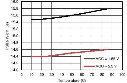
The SN74LVC1G123 has surprising temperature stability characteristics. The following plots show the pulse length over temperature. The external resistor and capacitor were not exposed to the same temperature in order to test only the change due to the semiconductor device. Frost would form on the board near freezing temperatures because of the test environment, so only data above 10°C was used. Since there is a large variation in pulse length over supply voltage (as indicated by the VCC vs K plots on the datasheet), the minimum and maximum recommended supply values are shown on each plot.
 Figure 4-4 Pulse Width Over
Temperature and Supply Voltage Range With Cext = 100 pF and
Rext = 100.7 kΩ
 Figure 4-6 Pulse Width Over
Temperature and Supply
 Voltage Range With Cext = 1 nF and Rext = 100.7 kΩ
 Figure 4-5 Pulse Width Over
Temperature and Supply Voltage Range With Cext = 500 pF and
Rext = 100.7 kΩ